Siemens 6AG1210-1PE28-2AL0 Power Supply Module Installation Guide: Wiring, Setup and Commissioning
Siemens 6AG1210-1PE28-2AL0 Power Supply Module installation requires correct AC input wiring, DC output verification, grounding, and PLC system commissioning to ensure stable power delivery. In industrial automation projects, many power-related failures are not caused by the power supply module itself but by incorrect voltage selection, poor wiring, overload conditions, or improper cabinet installation.
Siemens 6AG1210-1PE28-2AL0 Power Supply Module Application Overview
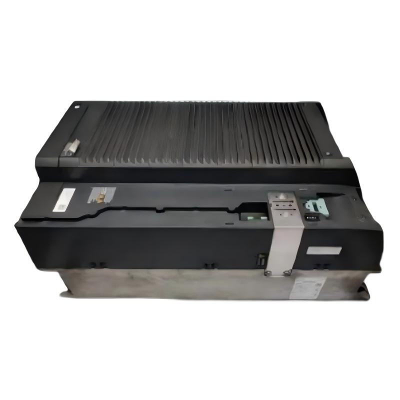
The Siemens 6AG1210-1PE28-2AL0 is a SIPLUS power supply module designed to provide reliable DC power for industrial automation systems. It is commonly used in PLC Controller installations where stable 24 V DC power is required for CPUs, I/O modules, sensors, communication devices, and field components.
Typical applications include:
- Siemens PLC control cabinets
- Industrial automation machines
- Process control systems
- Remote I/O stations
- Factory production equipment
- Distributed control applications
The basic power flow is:
AC Input Power → Siemens Power Supply Module → 24 V DC Distribution → PLC Controller / Module / Field Devices
A stable power supply is the foundation of reliable automation operation. Voltage fluctuation, overload, and poor grounding can create multiple PLC faults that appear unrelated to the power system.
Siemens 6AG1210-1PE28-2AL0 Power Supply Module Technical Specifications
Before installation, verify the module specifications and system requirements.
| Parameter | Specification |
|---|---|
| Manufacturer | Siemens |
| Model | 6AG1210-1PE28-2AL0 |
| Product Type | Power Supply Module |
| Product Family | SIPLUS / SIMATIC S7 Series |
| Input Voltage | AC 120/230 V |
| Output Voltage | 24 V DC |
| Output Power | 120 W |
| Output Current | 5 A |
| Installation Type | Industrial Control Cabinet |
| Application | PLC Power Distribution |
| Dimensions | 275 × 551 × 237 mm |
| Weight | 28 kg |
The power supply module is designed for industrial environments where stable operation under demanding conditions is required.
Siemens 6AG1210-1PE28-2AL0 Installation Preparation
Before mounting the power supply module, engineers should confirm the complete electrical system.
Preparation checklist:
- Verify incoming AC voltage
- Confirm cabinet installation space
- Check grounding system
- Calculate DC load requirements
- Confirm downstream device compatibility
- Inspect wiring components
Before installation, check:
- Module housing condition
- Terminal condition
- Mounting hardware
- Power cable insulation
- Environmental conditions
A common field mistake is selecting a power supply only according to output voltage while ignoring total current demand.
The correct engineering approach is:
Load Calculation → Power Supply Selection → Wiring → Voltage Verification → System Commissioning
Siemens 6AG1210-1PE28-2AL0 Power Wiring Installation
Correct power wiring is critical for safe operation.
The installation structure is:
AC Supply → Power Supply Input → Internal Conversion → 24 V DC Output → Automation Devices
During wiring, verify:
- AC phase connection
- Neutral connection
- Protective earth connection
- DC positive terminal
- DC negative terminal
- Cable cross-section
- Terminal tightening torque
Poor grounding can result in:
- PLC communication instability
- Sensor signal interference
- Unexpected controller restart
- Electrical noise problems
The protective earth connection should always be checked during installation.
Siemens 6AG1210-1PE28-2AL0 24V DC Output Setup
After wiring, measure the DC output before connecting the complete automation system.
Recommended checks:
| Test Item | Expected Condition |
|---|---|
| Output voltage | Approximately 24 V DC |
| Voltage stability | No abnormal fluctuation |
| Ground connection | Correct |
| Load capacity | Within rated range |
A practical commissioning method is:
- Power on the module without load.
- Measure DC output voltage.
- Connect PLC equipment.
- Monitor voltage under operating load.
This prevents damage caused by incorrect wiring or short circuits in downstream devices.
Siemens 6AG1210-1PE28-2AL0 PLC System Configuration
The Power Supply Module does not require software programming like a PLC Controller or communication module, but correct system configuration is still important.
Engineers should consider:
- Total connected load
- DC distribution layout
- Protection devices
- Backup power requirements
- Sensor and actuator consumption
A poorly designed DC distribution system may cause localized voltage drops.
For example:
A PLC CPU may operate normally while remote sensors experience unstable voltage because of insufficient cable sizing.
Siemens 6AG1210-1PE28-2AL0 Commissioning Procedure
During Commissioning, verify the complete power chain.
Recommended commissioning sequence:
Electrical Inspection → Input Voltage Test → DC Output Test → Load Connection → System Startup
Check:
- Input voltage accuracy
- DC output voltage
- Current consumption
- Temperature condition
- Alarm indicators
- Connected device operation
Monitor the power supply during actual machine operation because some overload problems only appear when all actuators are active.
Siemens 6AG1210-1PE28-2AL0 Field Commissioning Case
During one automation cabinet commissioning project, the PLC system repeatedly restarted when several field devices were activated simultaneously.
The maintenance team initially suspected a PLC Controller hardware problem.
The engineer measured the power system:
- Normal output voltage without load: 24.2 V DC
- Voltage during full load operation: 20.8 V DC
- Connected load current: Higher than calculated
Further inspection showed that multiple additional sensors and valves had been added after the original design.
After redistributing the DC load and correcting the power supply capacity calculation, the PLC system operated normally.
The problem was caused by insufficient power planning rather than a defective Siemens power supply module.
Siemens 6AG1210-1PE28-2AL0 Industrial Installation Considerations
For long-term reliability, pay attention to:
- Cabinet ventilation
- Ambient temperature
- Cable organization
- DC distribution design
- Electrical interference
Avoid installing the power supply near:
- High-power inverters
- Heat-generating equipment
- Strong electromagnetic interference sources
A clean cabinet design improves power stability and reduces unexpected automation downtime.
Siemens 6AG1210-1PE28-2AL0 Installation Troubleshooting
| Problem | Initial Diagnostic Direction |
|---|---|
| No DC output | Input power and wiring |
| PLC restart | Voltage stability and load |
| Output voltage low | Overload condition |
| Noise interference | Grounding and cable routing |
| Module overheating | Ventilation and load |
| System unstable | DC distribution design |