Siemens 6AG1443-5DX05-4XE0 Communication Processor Installation Guide (PROFIBUS Setup & Commissioning)
Siemens 6AG1443-5DX05-4XE0 Communication Processor Installation Guide for S7-400 PROFIBUS Systems
Siemens 6AG1443-5DX05-4XE0 Communication Processor installation problems are most often related to PROFIBUS configuration, bus wiring, address settings, and communication parameter mismatches rather than the communication processor itself. A correct installation and commissioning process ensures stable data exchange between SIMATIC S7-400 PLC systems, distributed I/O stations, operator panels, and industrial field devices.
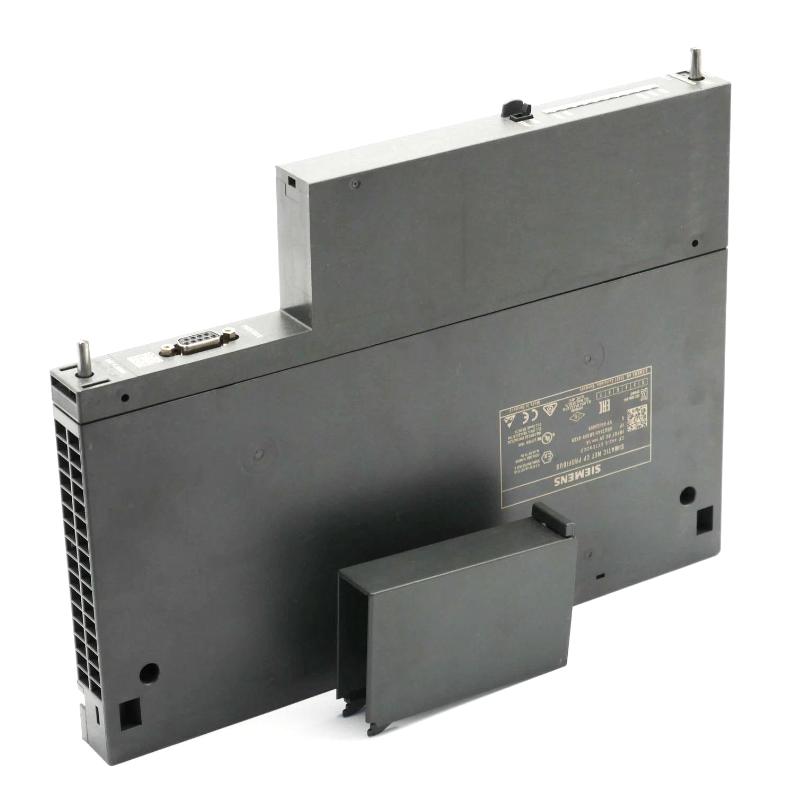
The Siemens 6AG1443-5DX05-4XE0 is a SIPLUS NET CP 443-5 Extended Communication Processor designed for connecting SIMATIC S7-400 automation systems to PROFIBUS networks. It supports PROFIBUS DP communication, S7 communication, PG/OP communication, and S5-compatible communication functions, making it suitable for demanding industrial environments.
This Installation Guide explains the practical engineering workflow used for Siemens 6AG1443-5DX05-4XE0 setup, including hardware preparation, PROFIBUS wiring, system configuration, commissioning verification, and field troubleshooting prevention.
Siemens 6AG1443-5DX05-4XE0 Communication Processor Installation Preparation
Before installing the Siemens 6AG1443-5DX05-4XE0 Communication Processor, engineers should evaluate the complete automation architecture.
A PROFIBUS communication system usually includes:
- SIMATIC S7-400 PLC rack
- CP 443-5 Extended communication processor
- PROFIBUS DP master network
- Remote I/O stations
- Field instruments
- HMI or engineering stations
The first step is confirming that the hardware design matches the actual production requirements.
Important preparation checks include:
| Inspection Item | Engineering Purpose |
|---|---|
| PLC rack compatibility | Confirm CPU and module arrangement |
| PROFIBUS topology | Verify device connection structure |
| Bus cable length | Avoid signal attenuation |
| Node address planning | Prevent address conflicts |
| Shield grounding | Reduce communication interference |
In one industrial upgrade project, engineers installed a new PROFIBUS communication processor but experienced unstable communication during startup. Hardware inspection showed that the module installation was correct, but the PROFIBUS cable shield was not connected properly at the cabinet grounding point. After correcting the grounding method, communication errors disappeared.
This case demonstrates that communication reliability depends on the entire system, not only the module itself.
Siemens 6AG1443-5DX05-4XE0 CP 443-5 Hardware Mounting and Electrical Setup
The Siemens 6AG1443-5DX05-4XE0 Communication Processor is installed as part of the SIMATIC S7-400 system. Mechanical installation should follow standard rack mounting practices.
Before powering the system, technicians should verify:
- Module position in the rack
- Backplane connection
- Power supply status
- Module seating condition
- Connector installation
The communication processor receives power through the S7-400 backplane bus. Technical specifications include a 5 V DC supply from the backplane and typical current consumption of approximately 0.6 A.
A practical installation inspection sequence:
Module Installation
        ↓
Backplane Connection Check
        ↓
Power Supply Verification
        ↓
PROFIBUS Cable Connection
        ↓
Hardware Configuration Download
Skipping any of these checks can create unnecessary commissioning delays.
Siemens 6AG1443-5DX05-4XE0 PROFIBUS Wiring and Network Configuration Setup
Correct PROFIBUS wiring is one of the most important parts of Siemens 6AG1443-5DX05-4XE0 Setup and Commissioning.
The module communicates through a PROFIBUS interface using a 9-pin Sub-D RS485 connection. The supported PROFIBUS transmission range depends on network configuration and can reach up to 12 Mbit/s.
During installation, engineers should check:
- PROFIBUS cable type
- Connector termination
- Bus polarity
- Shield connection
- Device address allocation
A common field mistake is incorrect termination at the beginning or end of the PROFIBUS segment.
Typical diagnostic logic:
Communication Failure
        ↓
Check CP Status LED
        ↓
Verify PROFIBUS Address
        ↓
Measure Bus Signal
        ↓
Check Termination Resistance
        ↓
Test Network Communication
In a commissioning case, a PROFIBUS network showed random station dropouts.
Measured condition:
Before correction:
- Communication retry events: 20–30/minute
- Network status: intermittent fault
Investigation found that two PROFIBUS connectors had incorrect termination settings.
After correction:
- Communication retry: 0 events
- Network operation: stable
Siemens 6AG1443-5DX05-4XE0 System Configuration and PROFIBUS Commissioning
After physical installation, Siemens 6AG1443-5DX05-4XE0 System Configuration must be completed in the engineering software environment.
The commissioning engineer normally performs:
- Hardware configuration creation
- CP module parameter assignment
- PROFIBUS network setup
- Slave device configuration
- Communication test
The configuration process should verify:
Hardware Layer
- Correct CP module identification
- Correct rack position
- Compatible configuration
Network Layer
- PROFIBUS address assignment
- Bus parameters
- Connected devices
Application Layer
- Data exchange function
- PLC communication blocks
- HMI communication
During one factory commissioning project, the CP module was recognized correctly, but the remote I/O station remained unavailable. Engineers compared the project configuration with the actual PROFIBUS device address and found a one-digit address mismatch.
After correcting the address, the distributed I/O immediately entered normal operation.
Siemens 6AG1443-5DX05-4XE0 Communication Processor Commissioning Validation
A complete Siemens 6AG1443-5DX05-4XE0 Commissioning process should include communication performance testing.
Recommended validation items:
| Test | Expected Result |
|---|---|
| CP module status | No diagnostic fault |
| PROFIBUS network | Stable communication |
| Remote I/O access | Normal data exchange |
| PLC program communication | Correct response |
| Long-term operation | No repeated errors |
Engineers often perform continuous running tests before releasing the system.
For example, during a process control system upgrade, the CP 443-5 Extended communication network was monitored for 72 hours. Communication diagnostics showed stable operation with no unexpected PROFIBUS interruptions.
Siemens 6AG1443-5DX05-4XE0 Communication Processor Maintenance Recommendations
Long-term reliability requires preventive maintenance.
Recommended checks:
- Inspect PROFIBUS connectors
- Check grounding condition
- Monitor diagnostic buffer
- Keep configuration backups
- Record network modifications
The Siemens 6AG1443-5DX05-4XE0 Communication Processor provides reliable PROFIBUS communication when installed with correct engineering practices and validated through systematic commissioning.