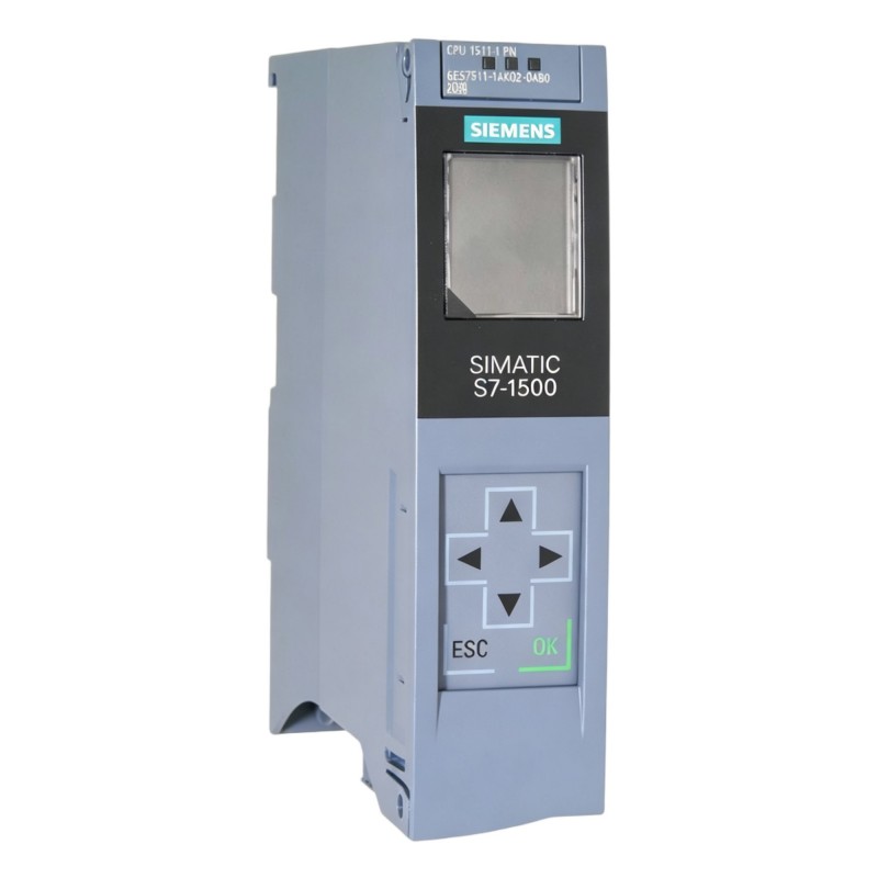
Siemens 6AG1511-1AK02-2AB0 PLC CPU Troubleshooting Guide (Fault Diagnosis & Repair)
Siemens 6AG1511-1AK02-2AB0 PLC CPU Troubleshooting for Unexpected STOP Conditions
Siemens 6AG1511-1AK02-2AB0 PLC CPU troubleshooting should begin with the actual failure pattern, especially when the controller unexpectedly changes operating state. A CPU entering STOP, losing communication, or halting a machine sequence does not automatically indicate processor hardware failure.
For this type of Fault Diagnosis, the most useful evidence comes from the PLC diagnostic information, power measurements, hardware status, communication condition, and the sequence of events immediately before the fault.
The objective is to determine whether the fault is located in the CPU, an attached module, the network, the control program, or the field equipment.
Siemens 6AG1511-1AK02-2AB0 PLC CPU STOP Fault Symptoms
A typical Siemens 6AG1511-1AK02-2AB0 fault may appear as:
- CPU unexpectedly changes operating state
- Machine sequence stops
- HMI shows a PLC connection alarm
- I/O operation becomes unavailable
- Diagnostic information appears in the engineering environment
The first question should be:
What happened immediately before the CPU stopped?
For example, if the CPU stops at the exact moment a specific field device is energized, that timing is valuable evidence. If the CPU stops after several hours of operation without a corresponding field event, power, thermal, communication, or software conditions deserve closer examination.
A useful troubleshooting record should contain:
| Observation | Recorded Information |
|---|---|
| Fault time | Exact timestamp |
| CPU state | RUN / STOP or other indicated state |
| Active diagnostic information | Recorded message |
| Supply voltage | Measured value |
| Network status | Normal / abnormal |
| Machine action before fault | Specific operation |
This transforms a vague complaint such as "PLC stopped" into a diagnosable event.
Siemens 6AG1511-1AK02-2AB0 PLC CPU Diagnostic Buffer Fault Analysis
The diagnostic information is one of the first places to investigate during Siemens 6AG1511-1AK02-2AB0 Troubleshooting.
Do not simply clear the diagnostic message and restart the PLC.
Instead, record:
- Event description
- Time of occurrence
- Related module
- Operating state
- Events immediately before and after the fault
Suppose a CPU repeatedly stops when a particular remote I/O station becomes unavailable. That pattern points toward communication or module integration rather than immediately indicating a processor failure.
The engineering process should therefore move outward from the CPU:
CPU Diagnostic Event
        ↓
Identify Related Module
        ↓
Check Communication
        ↓
Check Field Wiring
        ↓
Check External Device
        ↓
Confirm Root Cause
This approach prevents unnecessary CPU replacement.
Siemens 6AG1511-1AK02-2AB0 PROFINET Communication Fault Troubleshooting
Communication faults can appear to be CPU failures because the HMI or remote I/O may suddenly become unavailable.
Typical symptoms include:
- HMI connection interruption
- Remote device unavailable
- Intermittent data exchange
- Network diagnostic messages
- Machine sequence interruption
The troubleshooting process should begin with the physical network.
Check:
- Ethernet connectors
- Cable condition
- Switch status
- Network configuration
- Device availability
- Communication diagnostics
A field example involved an HMI that disconnected from the PLC approximately every 10 minutes.
Initial assumption:
PLC CPU communication fault
Measured evidence:
- CPU remained operational
- Network switch remained powered
- HMI connection dropped intermittently
- Ethernet connector showed mechanical looseness
After replacing the damaged connector, the connection remained stable during extended operation.
The Siemens 6AG1511-1AK02-2AB0 CPU had not been the source of the fault.
Siemens 6AG1511-1AK02-2AB0 Power-Related Fault Diagnosis
Power problems require measurement under actual operating conditions.
A PLC cabinet may show normal voltage when idle but experience a significant voltage drop when outputs, contactors, valves, or other loads are activated.
For example:
| Operating Condition | Measured Control Voltage |
|---|---|
| Cabinet idle | 24.2 VDC |
| Several outputs active | 22.9 VDC |
| Motor sequence started | 20.8 VDC |
If the CPU fault occurs at the same time as the voltage drop, the power system becomes a primary diagnostic target.
Engineers should inspect:
- Power supply capacity
- Terminal connections
- Fuses
- Distribution terminals
- Voltage drop across long cables
A stable CPU requires a stable control power system. Replacing the CPU before checking supply behavior can result in unnecessary maintenance costs and downtime.
Siemens 6AG1511-1AK02-2AB0 I/O Fault Diagnosis Without Replacing the CPU
A machine may stop because an input condition never becomes true, even though the PLC CPU is executing the program correctly.
For example, suppose a conveyor sequence waits for a position sensor.
The diagnostic chain should be:
Sensor Activated
      ↓
Field Signal Present?
      ↓
PLC Input Changes?
      ↓
Logic Condition Becomes TRUE?
      ↓
Output Command Generated?
      ↓
Actuator Responds?
If the sensor produces a signal but the PLC input remains unchanged, investigate the field wiring or I/O channel.
If the PLC input changes correctly but the program condition remains false, investigate the control logic or interlock.
If the output command is generated but the actuator does not respond, investigate the output circuit and field device.
This method separates PLC logic faults from electrical faults.
Siemens 6AG1511-1AK02-2AB0 Program and Configuration Troubleshooting
A configuration change can create a fault that appears immediately after a maintenance intervention.
Typical examples include:
- Hardware configuration modified
- Network device parameters changed
- Program block updated
- I/O assignment altered
- Commissioning project replaced with an older version
A practical repair process is to compare the current system against the last known working configuration.
The engineer should establish:
What changed?
When did it change?
What fault appeared afterward?
Can the previous configuration be verified?
This is often more informative than repeatedly restarting the PLC.
In one machine maintenance case, a communication fault appeared immediately after an engineering workstation was used to update the PLC project. Comparison with the previous project revealed a changed device parameter. Restoring the verified configuration removed the communication fault.
Siemens 6AG1511-1AK02-2AB0 CPU Hardware Fault Diagnosis
Only after external causes have been investigated should CPU hardware failure become the main hypothesis.
Hardware diagnosis should consider:
- CPU power condition
- Module recognition
- Diagnostic status
- Network interface behavior
- Reproducibility of the fault
A useful rule during repair is to look for repeatable evidence.
If the CPU operates normally with external communication removed but fails when a particular network device is connected, the external device deserves investigation.
If the same CPU fault occurs with the network, I/O, and application conditions isolated, the probability of an internal CPU-related problem becomes more relevant.
This is the difference between evidence-based Fault Diagnosis and component swapping.
Siemens 6AG1511-1AK02-2AB0 PLC CPU Repair Verification After Fault Recovery
After correcting the suspected root cause, do not stop at the first successful restart.
A proper Siemens 6AG1511-1AK02-2AB0 repair verification should include:
- CPU operating-state check
- I/O response test
- Communication test
- Machine sequence test
- Diagnostic monitoring
- Extended operating observation
For example, after correcting an intermittent communication problem, an engineer may monitor the system through multiple production cycles rather than declaring the repair complete immediately.
The purpose is to confirm that the original fault condition no longer occurs under the same operating circumstances.
Siemens 6AG1511-1AK02-2AB0 PLC CPU Troubleshooting Method for Maintenance Teams
A repeatable troubleshooting method can be summarized as:
Record the Symptom
        ↓
Check Diagnostic Information
        ↓
Verify Power
        ↓
Check Hardware and I/O
        ↓
Analyze Communication
        ↓
Review Program / Configuration
        ↓
Isolate External Equipment
        ↓
Test CPU Hardware
        ↓
Verify Repair Under Operation
The sequence should remain flexible. If diagnostic evidence clearly identifies a communication module or field device, there is no reason to spend hours testing unrelated CPU functions.
Siemens 6AG1511-1AK02-2AB0 Fault Diagnosis and Maintenance Conclusion
Siemens 6AG1511-1AK02-2AB0 PLC CPU Troubleshooting is most effective when the engineer treats the controller as one component within the complete automation system.
Unexpected stops, communication failures, and I/O problems can originate from power supplies, network connections, field devices, configuration changes, or application logic. Careful observation, measured electrical values, diagnostic records, and controlled testing provide a more reliable path to repair than immediate CPU replacement.
For maintenance teams, the most valuable result of a Siemens 6AG1511-1AK02-2AB0 Fault Diagnosis is not simply restoring RUN mode, but identifying the actual failure mechanism and verifying that the same condition cannot immediately reproduce the fault.