Siemens 6ES7521-1BH10-0AA0 数字输入模块 Siemens 6ES7521-1BH10-0AA0 Digital Input Module Installation Guide (Wiring & Commissioning)
Siemens 6ES7521-1BH10-0AA0 Digital Input Module Installation Guide for S7-1500 PLC Systems
Siemens 6ES7521-1BH10-0AA0 Digital Input Module installation requires accurate field wiring, correct hardware configuration, and reliable signal verification to ensure stable PLC operation. In industrial automation projects, digital input problems are frequently caused by incorrect terminal wiring, sensor power issues, or configuration mistakes rather than failure of the input module itself.
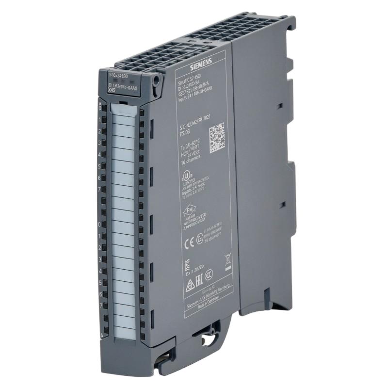
The Siemens 6ES7521-1BH10-0AA0 is a SIMATIC S7-1500 digital input module designed to collect binary field signals from industrial devices such as proximity sensors, limit switches, push buttons, and machine status contacts.
A reliable installation must verify the complete signal path:
Field Sensor → Terminal Wiring → Siemens 6ES7521-1BH10-0AA0 Input Channel → PLC Program → HMI/Control Logic
This Installation Guide explains practical engineering methods for mounting, wiring, configuring, and commissioning the Siemens 6ES7521-1BH10-0AA0 Digital Input Module in automation systems.
Siemens 6ES7521-1BH10-0AA0 Digital Input Module Installation Preparation
Before installing the Siemens 6ES7521-1BH10-0AA0, engineers should confirm the module application requirements and field signal types.
The preparation process should include:
- Confirming PLC rack configuration
- Checking input voltage compatibility
- Reviewing sensor types
- Verifying terminal assignment
- Preparing wiring documentation
- Inspecting cabinet grounding
Typical input devices connected to a digital input module include:
- Inductive proximity sensors
- Photoelectric sensors
- Emergency status contacts
- Push buttons
- Valve feedback switches
- Motor running feedback signals
A basic I/O mapping document should be prepared before wiring.
| PLC Address | Field Device | Signal Type | Function |
|---|---|---|---|
| I0.0 | Sensor | 24 VDC input | Position detection |
| I0.1 | Limit switch | Digital signal | Machine limit |
| I0.2 | Motor feedback | Contact signal | Running status |
This documentation becomes essential during commissioning and future Troubleshooting.
Siemens 6ES7521-1BH10-0AA0 Module Mounting and Hardware Setup
The physical installation of the Siemens 6ES7521-1BH10-0AA0 Digital Input Module should be completed according to the S7-1500 system arrangement.
Before mounting, check:
- DIN rail condition
- Module position
- Backplane connection
- Connector installation
- Cabinet space
- Cooling conditions
The module should be installed firmly with correct alignment to ensure reliable communication with the PLC backplane.
A practical installation sequence:
Prepare PLC Rack
       ↓
Install Module
       ↓
Check Backplane Connection
       ↓
Install Front Connector
       ↓
Complete Field Wiring
During one S7-1500 commissioning project, a newly installed digital input module showed no sensor signals. The module was powered correctly, but inspection found that the front connector had not been fully locked into position. After reconnecting the connector, all input channels operated normally.
Siemens 6ES7521-1BH10-0AA0 Digital Input Wiring Setup
Correct wiring is the most important part of Siemens 6ES7521-1BH10-0AA0 Setup.
Before connecting field devices, verify:
- Sensor supply voltage
- Signal polarity
- Terminal assignment
- Common reference connection
- Cable identification
For each input channel, confirm that the connected device provides the expected signal level.
Typical wiring verification:
Field Sensor Power
        ↓
Sensor Output Signal
        ↓
Input Terminal
        ↓
PLC Input Address
        ↓
Program Response
Common wiring mistakes include:
- Sensor connected to the wrong input terminal
- Missing 0V reference
- Incorrect sensor output type
- Damaged field cable
- Wrong I/O address mapping
A digital input module only processes the electrical signal it receives. If the field device does not provide the correct signal, replacing the module will not solve the problem.
Siemens 6ES7521-1BH10-0AA0 PLC Hardware Configuration and System Setup
After wiring, the Siemens 6ES7521-1BH10-0AA0 must be correctly configured in the PLC engineering environment.
The System Configuration should verify:
- Correct CPU hardware
- Correct module order
- Correct module identification
- Input address assignment
- Diagnostic settings
A typical engineering workflow:
Physical Module
       ↓
Hardware Configuration
       ↓
Input Address Mapping
       ↓
PLC Program
       ↓
Online Monitoring
The configured input address must match the physical wiring.
For example, if a proximity sensor is physically connected to the first input channel but the PLC program monitors another address, the sensor may appear faulty even though the hardware is functioning correctly.
Siemens 6ES7521-1BH10-0AA0 Digital Input Module Commissioning Procedure
The Siemens 6ES7521-1BH10-0AA0 Commissioning process should verify each input channel individually.
Recommended commissioning steps:
Sensor Signal Test
Check:
- Sensor activation
- Input LED response
- PLC monitoring status
Program Verification
Confirm:
- Correct input address
- Correct logic response
- Correct machine sequence
Field Operation Test
Verify:
- Real machine movement
- Feedback signals
- Interlock conditions
A practical commissioning method is to activate one sensor at a time and confirm the complete signal chain.
Example:
Activate Sensor
       ↓
Input LED ON
       ↓
PLC Online Status ON
       ↓
Logic Condition TRUE
       ↓
Machine Response
This method quickly identifies whether the problem exists in the sensor, wiring, module, or software.
Siemens 6ES7521-1BH10-0AA0 Digital Input Module Commissioning Case Study
During a machine startup, one position sensor connected to a Siemens 6ES7521-1BH10-0AA0 input channel did not trigger the automatic sequence.
The initial assumption was a defective input module.
The engineer performed signal tracing:
Initial observations:
- Sensor power: 24.1 VDC
- Sensor output: Normal
- Input terminal voltage: 0 V
Further inspection found that the sensor signal wire was connected to the wrong terminal during cabinet wiring.
After correcting the wiring:
- Input LED activated correctly
- PLC program detected the signal
- Machine sequence resumed normally
The module was operating correctly; the issue was a field wiring error.
Siemens 6ES7521-1BH10-0AA0 Digital Input Module Validation
After completing commissioning, validate the module under actual machine conditions.
Recommended checks:
| Validation Item | Purpose |
|---|---|
| Input channel test | Confirm every signal |
| Sensor response | Verify field devices |
| PLC monitoring | Confirm software mapping |
| Machine sequence | Validate operation |
| Diagnostic status | Check system health |
For production systems, perform repeated cycle testing to detect intermittent sensor or wiring issues.
Maintain updated:
- Electrical drawings
- I/O lists
- PLC project backup
- Commissioning records
These documents improve future maintenance efficiency.
Siemens 6ES7521-1BH10-0AA0 Digital Input Module Installation Best Practices
For long-term reliability:
- Keep wiring documentation updated
- Secure terminal connections
- Separate signal cables from high-noise power cables
- Inspect sensors regularly
- Maintain PLC project backups
The Siemens 6ES7521-1BH10-0AA0 Digital Input Module should be commissioned as part of the complete automation signal system. Proper Installation Guide procedures, accurate Setup, and systematic Commissioning help ensure reliable input signal processing in industrial PLC applications.