Siemens 6ES7521-1BH50-0AA0 Digital Input Module Installation Guide (Wiring & Commissioning)
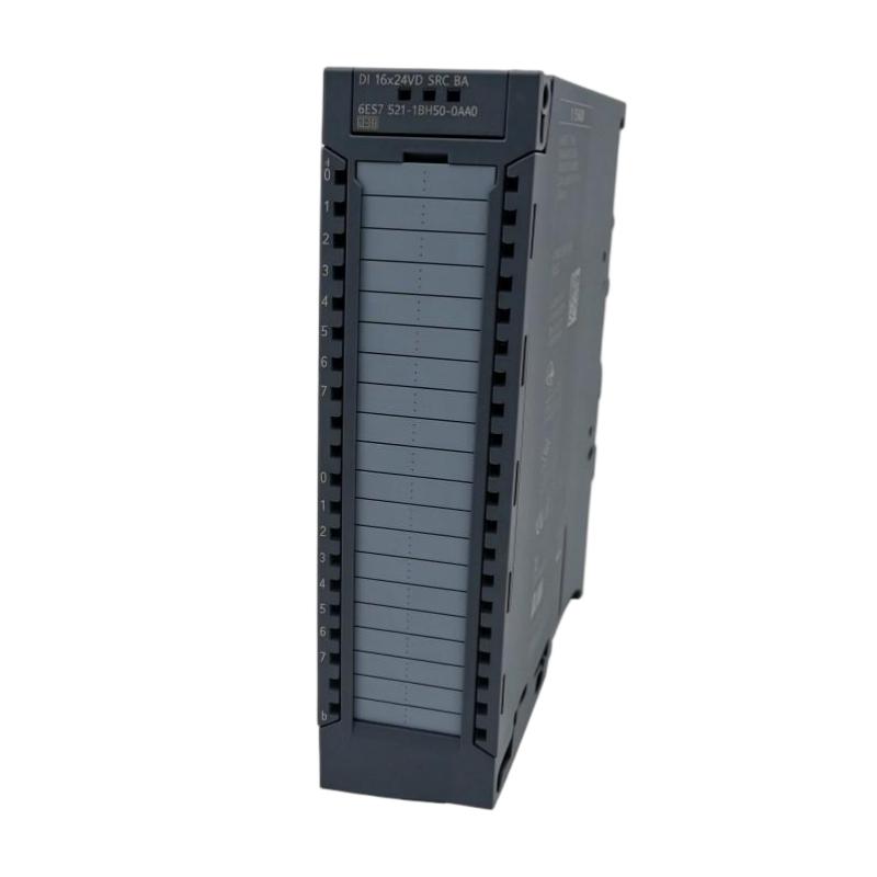
Siemens 6ES7521-1BH50-0AA0 Digital Input Module Installation Guide for S7-1500 Automation Systems
Siemens 6ES7521-1BH50-0AA0 Digital Input Module installation requires correct field wiring, accurate hardware configuration, and complete signal validation to ensure reliable PLC input processing. In industrial applications, digital input failures are frequently caused by sensor wiring mistakes, incorrect addressing, or unstable field signals instead of a defective PLC module.
The Siemens 6ES7521-1BH50-0AA0 Digital Input Module is designed for SIMATIC S7-1500 automation systems and is used to acquire binary signals from industrial devices including proximity sensors, switches, safety feedback contacts, and machine status signals.
A successful installation depends on the complete signal chain:
Field Device → Electrical Wiring → Siemens 6ES7521-1BH50-0AA0 Input Channel → PLC Program → Machine Control Logic
This Installation Guide focuses on practical engineering methods for module mounting, wiring preparation, System Configuration, and commissioning verification.
Siemens 6ES7521-1BH50-0AA0 Digital Input Module Application Planning
Before installing the Siemens 6ES7521-1BH50-0AA0, engineers should understand the role of each input signal in the automation system.
A digital input module does not create signals; it only receives and processes electrical states from external devices. Therefore, correct planning of field devices is essential.
Common applications include:
- Machine position detection
- Limit switch monitoring
- Motor running feedback
- Valve open/close confirmation
- Operator push buttons
- Safety-related status monitoring
Before wiring, prepare an I/O list containing:
| Input Address | Device | Signal Purpose |
|---|---|---|
| I0.0 | Proximity sensor | Object detection |
| I0.1 | Limit switch | Mechanical position |
| I0.2 | Contactor feedback | Motor status |
| I0.3 | Valve feedback | Process confirmation |
This documentation provides a reference during Siemens 6ES7521-1BH50-0AA0 Setup, Commissioning, and future Troubleshooting.
Siemens 6ES7521-1BH50-0AA0 Hardware Installation and Module Setup
The physical installation of the Siemens 6ES7521-1BH50-0AA0 Digital Input Module should follow the mechanical design of the S7-1500 PLC rack.
Before installation, inspect:
- DIN rail stability
- CPU and module arrangement
- Backplane connector condition
- Front connector installation
- Cabinet environmental conditions
A reliable hardware setup sequence:
Check PLC Rack
       ↓
Install 6ES7521-1BH50-0AA0 Module
       ↓
Verify Backplane Connection
       ↓
Install Front Connector
       ↓
Connect Field Wiring
During a machine commissioning project, engineers found that a newly installed digital input module appeared online in the engineering software but no input signals were detected. Investigation showed that the module was mechanically installed correctly, but the front connector was not fully inserted. After correcting the connection, all input channels became operational.
This type of issue demonstrates why physical verification is important during PLC installation.
Siemens 6ES7521-1BH50-0AA0 Digital Input Module Wiring Guide
Correct wiring is the foundation of Siemens 6ES7521-1BH50-0AA0 operation.
Before connecting field devices, verify:
- Signal voltage compatibility
- Input terminal assignment
- Sensor output type
- Common reference connection
- Cable identification
Typical digital input wiring path:
Sensor Power Supply
          ↓
Sensor Output Signal
          ↓
6ES7521-1BH50-0AA0 Input Terminal
          ↓
PLC Input Address
          ↓
Control Program Response
Common wiring problems include:
- Missing 0V reference
- Incorrect terminal connection
- Reverse polarity
- Incorrect sensor type
- Damaged field cable
A practical engineering method is to measure the actual voltage at the input terminal instead of assuming the sensor signal is reaching the PLC.
For example:
- Sensor output voltage: 24 VDC
- Terminal voltage: 0 VDC
This indicates a wiring problem between the sensor and module rather than an input channel failure.
Siemens 6ES7521-1BH50-0AA0 PLC System Configuration and Address Setup
After electrical installation, the Siemens 6ES7521-1BH50-0AA0 must be correctly configured in the PLC engineering environment.
The System Configuration should include:
- Correct hardware catalog selection
- Correct module position
- Correct input address assignment
- Diagnostic parameter verification
A typical configuration workflow:
Physical Installation
          ↓
Hardware Configuration
          ↓
Input Address Assignment
          ↓
PLC Program Mapping
          ↓
Online Monitoring
The physical input terminal and PLC software address must match.
A common commissioning mistake is testing a sensor while monitoring the wrong PLC address. The hardware may be working correctly, but the program is reading another input channel.
Siemens 6ES7521-1BH50-0AA0 Digital Input Module Commissioning Procedure
Siemens 6ES7521-1BH50-0AA0 Commissioning should verify each signal from the field device to the PLC logic.
Recommended verification process:
Field Signal Check
Confirm:
- Sensor activation
- Correct voltage level
- Stable signal output
Module Response Check
Observe:
- Input LED status
- Diagnostic information
- Channel response
PLC Logic Check
Verify:
- Input address
- Program reaction
- Machine sequence
A practical commissioning method:
Activate Field Device
          ↓
Check Module LED
          ↓
Monitor PLC Input
          ↓
Verify Control Logic
          ↓
Test Machine Operation
This method quickly separates electrical, hardware, and software-related problems.
Siemens 6ES7521-1BH50-0AA0 Digital Input Module Field Commissioning Case
During startup of an automated packaging machine, one position sensor connected to the Siemens 6ES7521-1BH50-0AA0 input module failed to trigger the next operation step.
The engineering team followed a signal diagnosis process.
Initial observations:
- Sensor supply voltage: 24.1 VDC
- Sensor indicator: ON
- PLC input status: OFF
The first assumption was an input module failure.
Further inspection found:
- Sensor output cable voltage: Normal
- Module terminal voltage: Incorrect
The cable connection inside the terminal block was loose.
After tightening the connection:
- Input status changed correctly
- Machine sequence recovered
- No module replacement was required
The case shows that proper Fault Diagnosis should follow the signal path rather than immediately replacing PLC hardware.
Siemens 6ES7521-1BH50-0AA0 Installation Validation and Maintenance
After commissioning, perform a complete validation test.
Recommended checks:
| Test Item | Purpose |
|---|---|
| Channel activation | Verify every input |
| Sensor response | Confirm field device operation |
| PLC monitoring | Confirm address mapping |
| Machine cycle test | Validate real operation |
| Diagnostic status | Detect hidden problems |
For long-term reliability:
- Keep wiring drawings updated
- Record input assignments
- Secure terminal connections
- Backup PLC projects
- Inspect sensors periodically
The Siemens 6ES7521-1BH50-0AA0 Digital Input Module should be installed as part of a complete PLC control system. Proper wiring, Setup, and Commissioning practices ensure stable industrial automation performance.