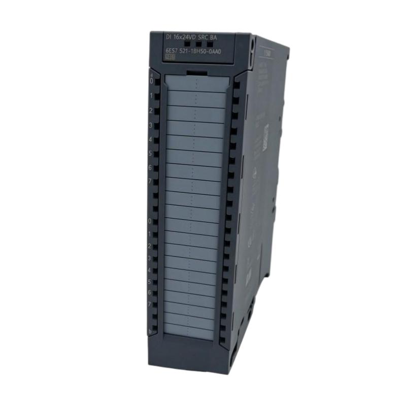
Siemens 6ES7521-1BH50-0AA0 Digital Input Module Troubleshooting Guide (Signal Fault Diagnosis & Repair)
Siemens 6ES7521-1BH50-0AA0 Digital Input Module Troubleshooting for PLC Input Failures
Siemens 6ES7521-1BH50-0AA0 Digital Input Module Troubleshooting requires systematic analysis of field signals, wiring conditions, PLC configuration, and module diagnostics. When a PLC input does not respond, the actual failure source may be outside the input module.
The correct Fault Diagnosis sequence is:
Field Device → Wiring → Input Terminal → Digital Input Channel → PLC Program → Machine Response
This approach prevents unnecessary module replacement and reduces machine downtime.
Siemens 6ES7521-1BH50-0AA0 Digital Input Module Fault Symptoms
Typical fault symptoms include:
- Input indicator remains OFF
- PLC program does not detect signal changes
- Input signal flickers unexpectedly
- Machine sequence stops
- Multiple inputs disappear simultaneously
Before troubleshooting, collect:
- PLC diagnostic information
- Input channel status
- Field device condition
- Voltage measurements
- Machine operating conditions
The timing of the fault often provides important clues.
For example:
- Fault only during motor operation → possible electrical interference
- Fault after maintenance work → possible wiring issue
- Fault affecting multiple channels → possible power or common connection problem
Siemens 6ES7521-1BH50-0AA0 Input Channel Fault Diagnosis Method
A digital input fault should be analyzed from the field side toward the PLC.
Diagnostic steps:
Check Field Device
        ↓
Measure Output Signal
        ↓
Check Module Terminal Voltage
        ↓
Monitor Input Status
        ↓
Verify PLC Logic
Example diagnostic logic:
If the sensor output is correct but the module terminal has no signal:
→ Check wiring.
If the terminal voltage is correct but PLC status remains OFF:
→ Check configuration or module condition.
This method avoids replacing functional components.
Siemens 6ES7521-1BH50-0AA0 Sensor Signal Loss Troubleshooting Case
A production line using Siemens S7-1500 experienced random machine stops caused by a missing position feedback signal.
The operator reported:
- Machine operated normally after reset
- Fault returned randomly
- No obvious hardware alarm
Engineers monitored the input signal during operation.
Measured values:
Normal operation:
- Sensor supply: 24.3 VDC
- Input signal: Stable ON/OFF switching
During fault:
- Sensor supply: 24.3 VDC
- Sensor output: Correct
- PLC input: Intermittent OFF state
Further inspection found mechanical vibration caused a loose terminal connection.
After repairing the wiring:
- Input signal remained stable
- Machine completed continuous production cycles
- Fault disappeared
The Siemens 6ES7521-1BH50-0AA0 module was functioning correctly.
Siemens 6ES7521-1BH50-0AA0 Intermittent Input Fault Troubleshooting
Intermittent input failures are difficult because the system may recover after restarting.
Common causes:
- Loose terminals
- Damaged cables
- Poor connector contact
- Sensor instability
- Electrical noise
During diagnosis, observe:
- When the fault appears
- Whether vibration affects the signal
- Whether temperature changes influence operation
- Whether nearby equipment switches at the same time
A useful maintenance method is recording the input state during the actual machine cycle rather than testing only when the machine is stopped.
Siemens 6ES7521-1BH50-0AA0 Incorrect PLC Configuration Fault Analysis
Sometimes the input hardware works correctly but the PLC program does not respond.
Check:
- Module order in hardware configuration
- Input address mapping
- PLC program references
- Downloaded hardware settings
Example:
Physical sensor connection:
Input channel 3
PLC program monitoring:
Input channel 5
Result:
- Sensor works
- Module works
- Program receives no expected signal
The problem is configuration mismatch.
Siemens 6ES7521-1BH50-0AA0 Multiple Input Channel Failure Diagnosis
When several channels fail simultaneously, investigate shared conditions.
Possible causes:
- Sensor power supply failure
- Missing reference voltage
- Common terminal problem
- Cabinet wiring issue
- PLC configuration error
Engineering judgment is important.
If ten sensors fail at the same moment, it is unlikely that ten independent sensors failed together. The investigation should focus on common electrical paths.
Siemens 6ES7521-1BH50-0AA0 Digital Input Module Replacement Decision
Before replacing the Siemens 6ES7521-1BH50-0AA0 Digital Input Module, confirm:
- Correct field signal reaches the terminal
- Wiring is verified
- Hardware configuration is correct
- Other channels operate normally
- Diagnostic information indicates module problems
A test signal from a verified source can help confirm whether the input channel processes signals correctly.
Hardware replacement should be the final step after evidence-based diagnosis.
Siemens 6ES7521-1BH50-0AA0 Repair Verification After Fault Correction
After completing repairs, verify the original failure condition.
Required checks:
- Activate the original sensor
- Monitor PLC input status
- Run automatic cycles
- Confirm stable operation
Record:
- Fault symptom
- Root cause
- Repair action
- Final verification result
This information improves future maintenance efficiency.
Siemens 6ES7521-1BH50-0AA0 Digital Input Module Troubleshooting Best Practices
Effective Siemens 6ES7521-1BH50-0AA0 Fault Diagnosis depends on following the complete signal path.
The recommended troubleshooting approach:
- Analyze symptoms
- Verify field signals
- Check wiring integrity
- Confirm PLC configuration
- Replace hardware only when necessary
By applying practical engineering Troubleshooting methods, maintenance teams can reduce downtime, avoid unnecessary PLC module replacement, and maintain reliable Siemens S7-1500 automation systems.