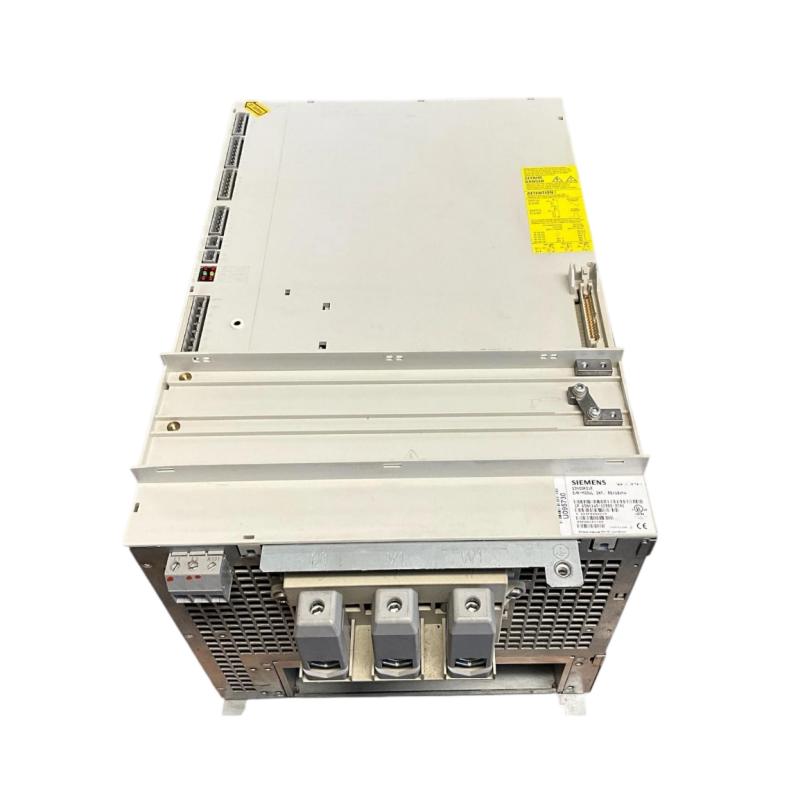
Siemens 6SN1145-1BB00-0EA0 Infeed/Regenerative Feedback Module Installation Guide
The Siemens 6SN1145-1BB00-0EA0 is a SIMODRIVE 611 infeed/regenerative feedback module designed for industrial drive systems. It is specified as a regulated, internally cooled module in the 80/104 kW class. Installation requires careful verification of the incoming power supply, compatible drive components, cooling arrangements, and regenerative operation requirements.
ADEGIS+1
1. Pre-Installation Checks for Siemens 6SN1145-1BB00-0EA0
Before installing the module, confirm the complete order number and compare it with the machine's electrical drawings and spare-parts records. The module belongs to a drive system in which the infeed unit, line-side components, and connected drive modules must be correctly matched.
Inspect the following before mounting:
Model identification: Verify the full part number, including the suffix
0EA0.System compatibility: Confirm that the module is approved for the installed SIMODRIVE 611 configuration.
Electrical supply: Check the incoming supply arrangement and associated protective devices against the equipment documentation.
Cooling: Inspect the cabinet ventilation paths and confirm that the specified internal-cooling arrangement can operate correctly.
Condition: Look for damaged connectors, cracked insulation, contamination, or signs of overheating.
This model is listed as discontinued, and successor variants exist. Do not assume that a newer suffix is a direct drop-in replacement without checking compatibility and any required configuration changes.
Radwell International+1
Safety requirement: Isolate the equipment, apply lockout/tagout, and follow the prescribed DC-link discharge procedure. Verify the absence of hazardous voltage with a suitably rated instrument before touching electrical connections.
2. Mechanical Mounting and Cooling Preparation
Install the Siemens 6SN1145-1BB00-0EA0 in its designated position within the drive cabinet. Its mounting arrangement must match the system design, and the module must be seated correctly without force.
During mounting:
Check the mounting area for debris, loose hardware, and signs of heat damage.
Confirm that adjacent drive components do not obstruct airflow.
Secure the module using the specified mounting hardware and tightening procedure.
Route cables so they do not place mechanical strain on connectors.
Check that cabinet fans, filters, and ventilation openings are in suitable condition.
Because this module uses internal cooling, cabinet temperature and airflow remain important even when the module itself contains its own cooling arrangement. Do not assume that a running fan alone proves adequate cooling.
3. Electrical Connections and Line-Side Components
The infeed/regenerative feedback module forms part of the drive system's power conversion arrangement. Incorrect line-side connections or incompatible associated components can prevent startup or cause protective shutdowns.
Before energizing the equipment, verify the following:
Incoming power connections match the approved electrical schematic.
Protective earth and bonding connections are correctly installed.
Associated line reactors and filters, where required by the system design, are the correct types and ratings.
Connectors are fully seated and wiring is secured.
Upstream circuit protection and disconnecting devices are appropriate for the installed configuration.
The DC-link and associated drive connections follow the prescribed Siemens connection sequence.
Never identify terminals by appearance alone. Use the documentation for the exact hardware version, and do not make or remove power connections while the equipment is energized.
4. System Configuration for Regenerative Operation
The Siemens 6SN1145-1BB00-0EA0 supports infeed and regenerative feedback functions within a compatible SIMODRIVE 611 system. During regenerative operation, energy returned by the connected drives must be handled by the designed power-conversion arrangement.
Before commissioning, review:
Configuration item | Engineering check |
|---|---|
Module compatibility | Confirm the infeed unit matches the installed drive system |
Supply conditions | Verify the line voltage and supply arrangement against the equipment specifications |
Associated components | Check the required line-side components and their ratings |
Operating mode | Confirm the documented settings for the intended infeed and regenerative operation |
Drive configuration | Verify connected modules and control arrangements |
Protection | Confirm that the applicable protective functions and upstream devices are in place |
Do not change switch positions or operating settings based on another SIMODRIVE module's configuration. The correct settings depend on the exact module version and the overall installation.
5. Commissioning the Siemens 6SN1145-1BB00-0EA0
Commissioning should proceed in stages, with each stage completed successfully before moving to the next.
Stage 1: Pre-energization inspection
Verify the wiring, grounding, mechanical mounting, cooling paths, and associated components. Remove loose tools and materials from the cabinet.
Stage 2: Initial power-up
Restore power using the machine's approved startup sequence. Monitor the system for abnormal indications, unexpected protective-device operation, unusual noise, or signs of overheating. Stop immediately if an abnormal condition occurs.
Stage 3: Diagnostic review
Check the available drive diagnostics and control-system status. Confirm that the infeed unit and associated components reach their expected operating states.
Stage 4: Controlled drive test
Where the machine's design permits, perform a controlled test with the connected drive system. Confirm the expected enable sequence and basic motion functions before testing more demanding operating conditions.
Stage 5: Regenerative operation verification
If the application uses regenerative braking or deceleration, verify the relevant operating sequence under controlled conditions. Check diagnostic status and confirm that the system behaves as documented.
Stage 6: Acceptance
Run a representative machine cycle while monitoring operating status, cabinet temperature, and recurring alarms. Record the results before returning the equipment to normal production.
6. Installation Case: Infeed Module Does Not Reach the Ready State
After maintenance, a machine's SIMODRIVE system powers up, but the connected drives remain unavailable. The maintenance team initially suspects an internal failure of the replacement infeed module.
The commissioning engineer checks the system methodically:
Confirms the exact module ordering number against the approved spare-parts record.
Reviews the diagnostic information to determine which startup condition is missing.
Checks the incoming supply and protective devices according to the electrical drawings.
Inspects the connections to associated line-side components.
Compares the installed hardware and configuration with the original commissioning records.
The investigation identifies an inconsistency in the associated line-side configuration. Once the discrepancy is corrected in accordance with the equipment documentation, the team repeats the startup sequence and confirms that the system reaches its expected operating state.
Practical lesson: A module that does not become ready is not necessarily defective. The supply arrangement, associated components, and startup conditions must be verified before replacing the unit again.
7. Installation Acceptance Checklist
Checkpoint | Acceptance criteria |
|---|---|
Module identity | Exact part number verified |
Mechanical installation | Correctly seated and secured |
Power connections | Checked against approved drawings |
Protective earth | Verified |
Line-side components | Compatible with the installed configuration |
Cooling | Airflow paths clear and cabinet conditions acceptable |
Diagnostics | No unresolved startup faults |
Functional test | Drive system operates as expected |
Records | Configuration and commissioning results documented |
8. Maintenance Recommendations
To maintain reliable operation of the Siemens 6SN1145-1BB00-0EA0, include the infeed module and its associated components in the drive system's preventive maintenance program.
Keep cabinet filters and ventilation paths clean.
Inspect accessible wiring and connectors during safely isolated maintenance.
Review recurring alarms and note the operating conditions associated with them.
Check for signs of overheating or deterioration around power connections.
Maintain accurate records of module replacements and configuration changes.
Verify the compatibility of replacement parts before installation.
A structured installation and commissioning process helps reduce startup delays and provides a clear baseline for future fault diagnosis.