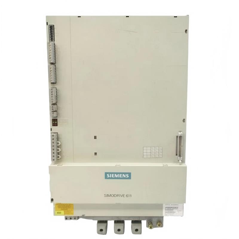
Siemens 6SN1145-1BB00-0EA1 Infeed/Regenerative Feedback Module Installation Guide
The Siemens 6SN1145-1BB00-0EA1 Infeed/Regenerative Feedback Module is associated with the SIMODRIVE 611 drive system used in industrial motion-control applications. Correct installation requires verification of the module's exact variant, incoming power connections, compatible drive components, cooling conditions, and commissioning requirements. Engineers should confirm the module's specifications against the equipment documentation before installation, particularly when replacing an existing unit or working with a legacy drive system.
1. Pre-Installation Inspection and Compatibility
Before installing the Siemens 6SN1145-1BB00-0EA1, compare its complete ordering number with the machine's approved spare-parts list and electrical drawings. Modules with similar designations may have different hardware characteristics, so compatibility should never be determined by appearance alone.
Complete the following checks:
Verify the complete part number and hardware identification.
Confirm compatibility with the installed SIMODRIVE 611 configuration.
Inspect the housing, connectors, terminals, and mounting surfaces for damage.
Check the condition of the incoming power supply and associated protective devices.
Review the installation requirements for associated line-side components.
Confirm that the cabinet's cooling arrangement is suitable for the installed module.
The 0EA1 suffix must be verified independently against the installed system's documentation. Do not assume that it is interchangeable with the 0EA0 version without checking the manufacturer's compatibility information.
Electrical safety: Isolate all relevant power sources, apply lockout/tagout, follow the specified DC-link discharge procedure, and verify the absence of hazardous voltage before touching electrical connections.
2. Mechanical Mounting and Cabinet Preparation
The module must be installed in the designated position within the drive cabinet. Correct seating and secure mounting help prevent connection problems and unnecessary mechanical stress.
Follow this procedure:
Inspect the mounting area and remove dust or loose materials using an approved method.
Confirm that the mounting points and mechanical guides match the module.
Position the module carefully without forcing connectors or fixing points.
Secure the module according to the manufacturer's specified procedure.
Ensure that adjacent components do not obstruct cooling airflow.
Check that cable routing does not place strain on terminals or connectors.
If the module does not seat correctly, stop and investigate possible alignment issues, contamination, or a hardware mismatch. Do not modify mounting points to force installation.
3. Electrical Wiring and Power Connection Checks
The infeed/regenerative feedback module operates as part of a larger drive power system. Its electrical connections must match the approved system design, including the incoming supply, protective grounding, and associated drive components.
Before energization, verify the following:
Inspection item | Required action |
|---|---|
Incoming power | Check the connection arrangement against the electrical drawings |
Protective grounding | Verify the specified grounding and bonding connections |
Line-side components | Confirm the required components are installed and correctly rated |
Power connections | Inspect accessible terminals and connectors for damage or poor contact |
Control wiring | Confirm the wiring matches the system configuration |
Protective devices | Verify that upstream protection matches the approved design |
Use the documentation for the exact module variant to establish terminal assignments and permissible electrical conditions. Do not transfer wiring assumptions from another module in the same product family.
4. Verify System Configuration Before Startup
Before commissioning, confirm that the module is suitable for the installed drive arrangement and that all associated components are correctly configured.
Important checks include:
The infeed module matches the approved system configuration.
The incoming supply meets the documented requirements.
Associated line-side components are compatible with the drive arrangement.
Connected drive modules and control hardware are correctly identified.
Applicable protection settings match the machine's approved configuration.
Any replacement-related configuration procedures have been completed.
Record existing settings before making permitted changes. Avoid modifying multiple parameters simultaneously, because doing so makes subsequent fault diagnosis more difficult.
5. Siemens 6SN1145-1BB00-0EA1 Commissioning Procedure
Commissioning should proceed in stages so that problems can be identified before the equipment enters normal production.
Stage 1 — Pre-energization review
Check mounting, grounding, wiring, cooling paths, and associated components. Ensure that all tools and loose materials have been removed from the cabinet.
Stage 2 — Initial energization
Restore power according to the machine's approved procedure. Observe the drive system for abnormal indications, unusual noise, unexpected protective-device operation, or signs of overheating. Stop immediately if an abnormal condition occurs.
Stage 3 — Infeed status verification
Review the available drive diagnostics and confirm that the infeed system reaches its expected operating state. Investigate any unresolved startup messages before proceeding.
Stage 4 — Controlled functional test
Enable the connected drive system under the conditions permitted by the machine's safety procedures. Confirm the intended enable sequence and basic operational response.
Stage 5 — Regenerative operation test
Where the application uses regenerative braking or deceleration, test the relevant operating sequence under controlled conditions. Monitor the diagnostic status and confirm that the system behaves as documented.
Stage 6 — Acceptance
Run a representative machine cycle and review the operating status, temperature conditions, and fault history. Record the test results before releasing the equipment for production.
6. Installation Case: Connected Drives Remain Disabled After Replacement
After a scheduled maintenance shutdown, an engineer installs a Siemens 6SN1145-1BB00-0EA1 module. The cabinet powers up, but the connected drives do not reach their expected ready state.
Instead of immediately declaring the replacement defective, the engineer follows a structured investigation:
Checks the full module ordering number against the approved spare-parts record.
Reviews the diagnostic history to identify the missing startup condition.
Verifies the incoming supply and protective circuits using the approved drawings.
Inspects the connections to the associated line-side components.
Compares the installed hardware and configuration with the original commissioning records.
The investigation identifies a discrepancy in the associated system configuration. After the discrepancy is corrected according to the equipment documentation, the engineer repeats the startup procedure and verifies the expected operating status.
Engineering takeaway: A drive system that remains disabled after module replacement may have a configuration or associated-component issue rather than an internal module defect. Verify the entire infeed arrangement before replacing the module a second time.
7. Installation Acceptance Checklist
Checkpoint | Acceptance criteria |
|---|---|
Part number | Complete ordering number verified |
Mechanical mounting | Module correctly seated and secured |
Electrical wiring | Connections match approved drawings |
Protective grounding | Grounding arrangement verified |
Associated components | Correct types and ratings confirmed |
Cooling | Ventilation paths clear |
Diagnostic status | No unresolved startup faults |
Functional testing | Required drive functions operate correctly |
Documentation | Installation and test results recorded |
8. Maintenance Recommendations
Regular inspection of the Siemens 6SN1145-1BB00-0EA1 and its surrounding drive system can reduce avoidable downtime.
Keep cabinet filters and cooling passages clean.
Inspect accessible power connections during safely isolated maintenance.
Monitor recurring infeed and drive-system alarms.
Check for discoloration, unusual heating, or deterioration around connections.
Record module replacements and configuration changes.
Verify the compatibility of replacement parts before installation.
A documented commissioning process provides a useful baseline for future maintenance and helps distinguish installation problems from faults that develop during operation.