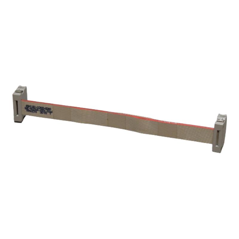
Siemens 6SN1161-1CA00-0DA0 Drive Bus Cable Troubleshooting Guide for Communication Faults
Siemens 6SN1161-1CA00-0DA0 drive bus cable troubleshooting should begin with connector integrity, cable compatibility, and the SIMODRIVE 611 module configuration before a drive controller is declared defective. An incorrectly seated connector, damaged cable, or mismatch between the installed hardware and the cable specification can interrupt communication and prevent the expected drive status from appearing at the control system.
The objective of Fault Diagnosis is to distinguish a cable-related problem from a drive-module, control-unit, or configuration fault using evidence from the installed machine.
Siemens 6SN1161-1CA00-0DA0 Drive Bus Fault Symptoms
A suspected drive-bus problem may present in several ways:
One or more drive components are not recognized correctly.
A drive communication alarm appears after cabinet maintenance.
An axis cannot enter its normal operational state.
An intermittent fault occurs following mechanical movement or cabinet servicing.
Replacing a component does not resolve the original alarm.
These symptoms do not prove that the 6SN1161-1CA00-0DA0 cable is defective. Similar behavior can result from control-unit faults, incorrect hardware assignments, connector damage, or other problems within the drive system.
The first task is to record the exact alarm text, affected axes, operating conditions, and the time at which the fault first appeared.
Siemens SIMODRIVE 611 Fault Diagnosis: Follow the Evidence
A useful troubleshooting method is to compare three sources of evidence: the physical installation, the control system's diagnostic information, and the relationship between the fault and recent maintenance activity.
For example, if several previously functional axes become unavailable immediately after a cable replacement, verify the cable part number and connector placement before investigating individual motors. If only one axis is affected and the other drive components remain operational, focus the inspection on the affected connection and its associated hardware.
The 6SN1161-1CA00-0DA0 is intended for a 300 mm module-width application. A cable that physically fits but does not match the intended configuration should not be accepted as a valid substitute.
Case-Based Troubleshooting of the Siemens 6SN1161-1CA00-0DA0
Representative fault pattern: communication failure following maintenance
A machine is stopped for cabinet servicing. After the system is restarted, the control displays a drive-related communication alarm.
Rather than replacing the controller immediately, the engineer reviews the maintenance record and discovers that the drive-bus connection was disturbed during the work.
The diagnostic process proceeds as follows:
Compare the installed cable number with the approved parts list.
Inspect both connectors for incomplete engagement or physical damage.
Check whether the module arrangement has changed.
Review the control system's alarm history after the physical inspection.
Perform a controlled restart and compare the resulting status with the pre-maintenance baseline.
If the alarm clears after correcting a verified connection problem, the evidence supports a connection-related cause. If the alarm remains, continue with the system-specific diagnostic procedure instead of assuming that another cable replacement will solve it.
This is a representative troubleshooting scenario, not a claim of a documented repair on a particular Siemens installation.
Siemens 6SN1161-1CA00-0DA0 Cable Inspection and Electrical Safety
Drive-bus cable repair should distinguish between a connector that is incorrectly seated and a cable assembly that has sustained physical damage.
Check for:
Cracked or deformed connector housings.
Bent, contaminated, or damaged contacts.
Cuts, compression marks, and excessive bending.
Evidence of heat exposure or contact with moving cabinet components.
Incorrect routing introduced during earlier maintenance.
Do not repair damaged conductors or connectors with improvised splices unless an approved Siemens procedure explicitly permits that repair. Replacing a damaged cable with the correct assembly is generally preferable to introducing an unvalidated connection into a drive communication path.
All physical inspection and reconnection must be performed under the applicable electrical isolation and machine-safety procedures.
Siemens 6SN1161-1CA00-0DA0 Troubleshooting Measurements and Signal Analysis
Unlike a sensor fault, a drive-bus cable problem cannot necessarily be diagnosed by measuring a single analog value such as 4–20 mA or vibration velocity. The appropriate diagnostic evidence depends on the bus design and the connected drive hardware.
Use the following decision framework:
Observation | Engineering interpretation | Recommended action |
|---|---|---|
Fault begins immediately after cable replacement | Incorrect part or connection is plausible | Verify order number and connector placement |
Cable shows visible damage | Physical cable failure is possible | Replace with a compatible assembly |
Fault persists after connection inspection | Cable may not be the root cause | Review drive and control diagnostics |
Multiple components become unavailable together | A shared connection or configuration issue is possible | Examine the common communication path |
Alarm returns intermittently | An unstable connection or another system fault remains possible | Correlate alarm timing with operating conditions |
Do not apply an assumed resistance, voltage, or continuity threshold without consulting the applicable technical documentation. Likewise, avoid disconnecting a live drive-bus cable as a diagnostic shortcut. Any electrical test must be appropriate for the interface and approved service procedure.
Siemens 6SN1161-1CA00-0DA0 Recovery and Verification
After correcting the identified problem, repeat the checks that originally failed. Verify that the control system recognizes the expected drive components, that the original alarm no longer recurs, and that the affected axis completes the prescribed functional test.
A single successful power cycle is not sufficient evidence that an intermittent fault has been eliminated. Where practical, observe the machine through a controlled operating period and review the diagnostic history for recurring communication errors.
Record the replacement part number, the identified root cause, the corrective action, and the commissioning result. This information helps distinguish a recurring cable problem from a separate failure in the drive controller or system configuration.
Siemens 6SN1161-1CA00-0DA0 Fault Diagnosis: When to Investigate Other Components
If the correct cable is securely connected and the communication fault remains, expand the investigation systematically.
Check whether the installed module arrangement agrees with the approved System Configuration. Review the relevant control-unit and drive-module diagnostics, and establish whether the fault affects a single connection or a wider section of the system.
Do not replace a controller solely because a communication alarm remains active. A defensible repair decision should be supported by diagnostic evidence that narrows the fault to the relevant component.
The key principle in Siemens 6SN1161-1CA00-0DA0 Troubleshooting is to verify the cable and its installation first, then escalate to drive hardware and configuration checks only when the observed evidence justifies doing so.