ABB 1MRK000167-ACr06 Printed Circuit Board Troubleshooting Guide (Hardware Failure Diagnosis)
When ABB 1MRK000167-ACr06 PCB Faults Affect Equipment Operation
ABB 1MRK000167-ACr06 printed circuit board faults can cause abnormal equipment startup, internal communication failures, hardware recognition problems, or unexpected diagnostic alarms. However, these symptoms do not necessarily indicate that the PCB itself has failed. Power supply instability, connector contact problems, incompatible hardware revisions, and external circuit conditions should be investigated before replacing the board.
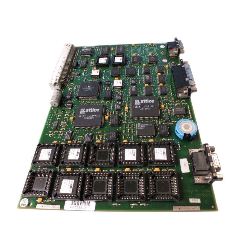
The 1MRK000167-ACr06 is an ABB electronic PCB associated with processing-related hardware in the 1MRK000167 family. It operates as part of its designated host equipment and depends on the correct internal connections and system configuration.
Effective Troubleshooting therefore requires examining the complete equipment architecture rather than treating the PCB as an independent controller.
Initial Fault Assessment of ABB 1MRK000167-ACr06
The first task is to identify when the abnormal behavior occurs.
A failure immediately after power-up suggests a different diagnostic direction from an intermittent fault that develops after several hours of operation.
Record the following information before performing any repair:
Diagnostic observation | Investigation direction |
|---|---|
Equipment fails during startup | Power supply and initialization |
Hardware identification error | PCB revision and compatibility |
Internal communication alarm | Connector and communication interface |
Intermittent equipment reset | Power stability and electronic condition |
Fault after prolonged operation | Temperature and component condition |
Alarm following board replacement | Configuration and installation verification |
If the original equipment provides an event log or diagnostic history, preserve it before resetting alarms or changing hardware.
The timing and sequence of fault events can provide valuable evidence about the underlying failure.
Fault Analysis: ABB 1MRK000167-ACr06 Internal Communication Failure
One possible fault pattern is the loss of communication between the replacement PCB and other internal equipment assemblies.
The symptoms may include:
Internal communication alarms.
Missing hardware identification.
Incomplete equipment initialization.
Intermittent diagnostic warnings.
Failure of dependent functions.
The investigation should begin with the physical interface.
Inspect the board connectors, mounting position, and associated internal connections. A connector that appears mechanically installed may still have poor electrical contact.
Next, compare the installed board identification with the equipment maintenance documentation.
The complete suffix is important because different hardware variants may have different electrical or functional characteristics.
Engineering case scenario:
After replacing an internal ABB processing-related PCB, an equipment assembly completes its initial power-up but reports an internal communication warning.
The engineer first checks whether the board is fully seated. The next inspection focuses on connector condition and the identification of the replacement assembly.
If the physical connections are satisfactory, the investigation moves to firmware compatibility and host equipment configuration.
Replacing additional internal modules without completing these checks can introduce more variables and complicate Fault Diagnosis.
Diagnosing ABB 1MRK000167-ACr06 Power-Related Failures
Unstable internal power is another possible cause of abnormal PCB behavior.
A processing-related board may exhibit intermittent resets or incomplete startup when its supply rails are outside the host equipment's specified operating limits.
Possible causes include:
An unstable internal power supply.
High-resistance connector contacts.
Damaged PCB power connections.
Excessive temperature inside the equipment.
A short circuit in an associated assembly.
The engineer should consult the host equipment's electrical drawings to identify the correct test points and nominal supply values.
Do not assume a standard voltage assignment based solely on the PCB part number.
Use appropriately rated measurement equipment and compare measured values against the manufacturer's electrical specifications.
If the supply remains stable at its source but drops at the PCB interface, inspect the connecting path before concluding that the board is defective.
PCB Inspection: Identifying Physical Damage and Component Deterioration
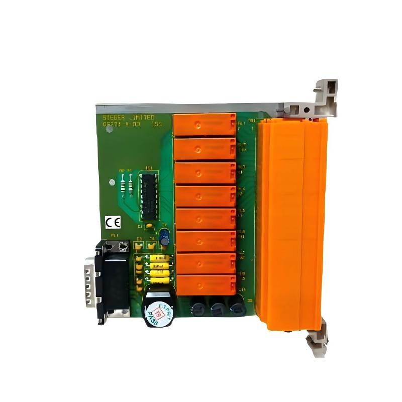
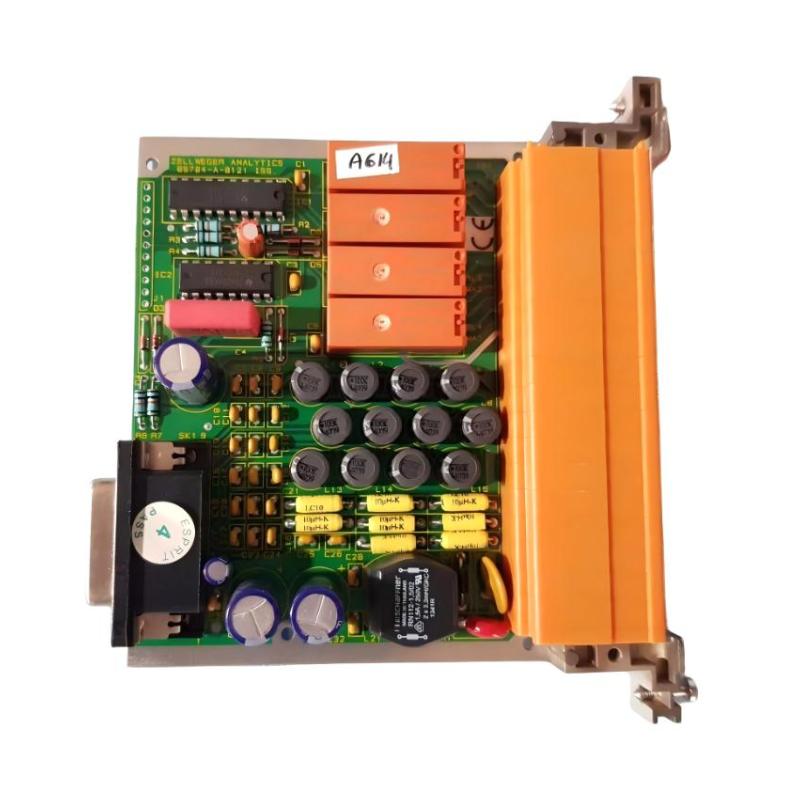
Visual inspection is an important part of 1MRK000167-ACr06 hardware Fault Diagnosis.
A damaged PCB may show visible signs of electrical or environmental stress, although some electronic failures leave no obvious physical evidence.
Pay particular attention to:
Burn marks around electronic components.
Discolored circuit board areas.
Cracked solder joints.
Corrosion around connectors.
Damaged conductive tracks.
Swollen or leaking capacitors, where fitted.
Mechanical damage caused during previous maintenance.
A magnified inspection can help identify small cracks around soldered connectors.
However, a clean-looking board should not automatically be considered electrically healthy. Internal semiconductor failures and intermittent component defects may require specialist electronic testing.
Distinguishing PCB Hardware Failure from System Configuration Errors
An incorrect system configuration can produce symptoms similar to an electronic hardware failure.
For example, a replacement board may be electrically functional but not recognized because its hardware revision or firmware is incompatible with the host equipment.
The following comparison helps narrow the investigation:
Observed condition | Likely diagnostic direction |
|---|---|
Board not recognized | Hardware identification and connector checks |
Repeated initialization failure | Power supply and startup diagnostics |
Communication warning | Internal interface and configuration |
Fault appears after firmware changes | Version compatibility |
Intermittent operation | Electrical contacts and power stability |
Visible component damage | PCB hardware evaluation |
The correct System Configuration must be confirmed using the host equipment's official documentation.
Avoid attempting firmware updates or parameter restoration until the board identity and supported software version have been verified.
ABB 1MRK000167-ACr06 Troubleshooting After PCB Replacement
A fault appearing immediately after replacement deserves a separate investigation.
The maintenance engineer should compare the removed PCB and replacement assembly side by side.
Check:
Complete part number.
ACr06 revision identification.
Connector positions.
Component layout.
Board mounting arrangement.
Applicable firmware requirements.
Do not assume that another 1MRK000167 variant is a suitable substitute.
For example, the ACr06 and ACr11 designations identify different versions. Their interchangeability must be confirmed through ABB equipment documentation or an authorized compatibility assessment.
If the replacement board is correct, inspect the installation and restore the required configuration using the approved procedure.
Repair and Recovery Options for ABB 1MRK000167-ACr06
Once the fault has been isolated, select a repair method based on the actual failure mechanism.
Identified issue | Corrective action |
|---|---|
Loose connector | Inspect and correctly reseat the connection |
Connector contamination | Clean using an approved electronics maintenance procedure |
Unstable internal supply | Diagnose the associated power supply circuit |
Incorrect hardware revision | Obtain the compatible PCB |
Firmware incompatibility | Follow the approved firmware procedure |
Damaged PCB tracks | Refer for qualified electronic repair evaluation |
Burned components | Investigate the original electrical cause before replacement |
Persistent hardware failure | Replace with a verified compatible assembly |
Component-level repair should only be performed by qualified electronics technicians with suitable diagnostic equipment and access to the applicable circuit documentation.
For protection-related equipment, an improvised repair or unverified component substitution can compromise system reliability.
Post-Repair Testing and Equipment Commissioning
After correcting the problem, the PCB should be tested within its designated host equipment.
A complete recovery process should verify more than the disappearance of the original alarm.
The commissioning engineer should confirm:
Normal equipment startup.
Correct PCB hardware recognition.
Stable internal power.
Normal internal communication.
Completion of required self-diagnostics.
Correct restoration of equipment configuration.
Successful functional testing of dependent equipment functions.
Where the board participates in a protection system, all applicable protection-function tests must follow the approved testing procedure.
Do not return protection equipment to operational service solely because its diagnostic alarms have cleared.
Preventing Repeated ABB 1MRK000167-ACr06 Hardware Failures
Repeated PCB failures may indicate an underlying equipment problem rather than poor board quality.
If the same failure returns after replacement, investigate the surrounding operating environment.
Review cabinet temperature, ventilation, humidity, contamination, power quality, grounding, and mechanical vibration.
Maintenance records should also include the complete replacement part number and revision, the original fault symptoms, diagnostic findings, and final test results.
This information helps identify recurring failure patterns and reduces unnecessary replacement of healthy electronic assemblies.
Long-Tail Keywords for ABB 1MRK000167-ACr06 Troubleshooting
ABB 1MRK000167-ACr06 troubleshooting guide
ABB 1MRK000167-ACr06 PCB fault diagnosis
ABB printed circuit board hardware failure
ABB processing board communication fault
1MRK000167-ACr06 PCB replacement problems
ABB industrial control PCB repair
ABB electronic board startup failure
ABB PCB hardware compatibility troubleshooting
ABB protection equipment circuit board diagnostics
ABB 1MRK000167 hardware revision compatibility