1MRK000167-ACr11 Printed Circuit Board Installation Guide (Hardware Setup & Commissioning)
ABB 1MRK000167-ACr11 PCB Installation and Hardware Overview
The ABB 1MRK000167-ACr11 printed circuit board must be verified against the host equipment's hardware configuration before installation. Correct part-number identification, connector compatibility, mounting position, and firmware requirements are essential to prevent hardware recognition errors and abnormal startup behavior.
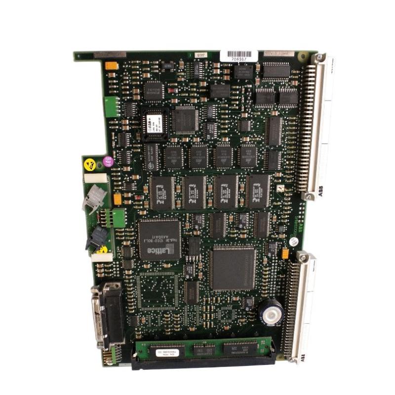
The 1MRK000167-ACr11 belongs to ABB's 1MRK000167 electronic hardware family and is designed for integration into compatible industrial protection and control equipment. It is an internal PCB assembly rather than an independent PLC or standalone controller.
When preparing an ABB 1MRK000167-ACr11 Installation Guide, the most important consideration is to distinguish the ACr11 version from other boards sharing the same base number. A visually similar PCB does not necessarily have identical hardware characteristics or system compatibility.
Identifying the ABB 1MRK000167-ACr11 Before Installation
Before beginning maintenance, confirm the complete part number on the original assembly and compare it with the replacement board.
The following information should be recorded:
Identification item | Verification requirement |
|---|---|
Manufacturer | ABB |
Model | 1MRK000167-ACr11 |
Product type | Printed Circuit Board |
Product family | 1MRK000167 |
Hardware designation | ACr11 |
Host equipment | Confirm original equipment model |
Connector arrangement | Compare with equipment drawings |
Firmware compatibility | Verify with host system documentation |
Installation position | Confirm designated PCB location |
The ACr11 suffix must remain part of the replacement identification. In particular, do not assume that ABB 1MRK000167-ACr06 and 1MRK000167-ACr11 are interchangeable.
Preparation for ABB 1MRK000167-ACr11 Replacement
A controlled installation begins with documenting the existing equipment condition.
If the original PCB is still accessible, record its identification, active diagnostic messages, and any abnormal operating behavior. Where supported, save the host equipment configuration before removing the board.
Prepare the following:
Verified ABB 1MRK000167-ACr11 replacement PCB.
Original equipment electrical and assembly drawings.
ESD protection equipment.
Suitable maintenance tools.
Connector identification labels.
Equipment configuration and service records.
For protection and control installations, follow the approved maintenance isolation procedure. Isolate all relevant power sources and verify that potentially hazardous external circuits have been made safe.
Do not rely on switching off the main supply alone when the equipment includes independent auxiliary supplies or external electrical connections.
ESD Protection During 1MRK000167-ACr11 PCB Handling
Electrostatic discharge can damage sensitive electronic components without producing visible physical damage.
Before handling the ABB PCB, establish an appropriate ESD-protected working environment.
The technician should:
Wear a properly grounded ESD wrist strap.
Use an approved antistatic work surface.
Keep the replacement PCB inside its antistatic packaging until required.
Hold the circuit board by its edges.
Avoid touching connector contacts and component pins.
Prevent mechanical stress during removal and installation.
A board that passes an initial visual inspection may still have suffered ESD damage. Therefore, careful handling must be maintained throughout the entire replacement process.
Mechanical Installation and Connector Verification
The mechanical installation of the 1MRK000167-ACr11 should follow the host equipment's assembly drawings.
Before inserting the PCB, inspect the designated mounting position and mating connectors.
Pay particular attention to:
Connector alignment.
Bent or recessed contacts.
Contamination and oxidation.
Damaged mounting points.
Loose internal wiring.
Evidence of previous overheating.
The replacement board should fit its designated position without excessive mechanical force.
If the connector arrangement differs from the removed PCB, stop the installation and verify the replacement part number and equipment compatibility.
Do not modify connector positions or mechanical mounting features to make an unverified replacement fit.
ABB 1MRK000167-ACr11 Hardware Configuration and System Setup
After the PCB is physically installed, the next requirement is confirming that the host equipment can recognize and operate with the replacement hardware.
The exact configuration procedure depends on the ABB host equipment in which the board is installed. There is no safe basis for assigning universal DIP-switch settings, communication parameters, or firmware values from the PCB part number alone.
During System Configuration, verify:
Supported hardware revision.
Host equipment compatibility.
Firmware version requirements.
Internal communication connections.
Required initialization procedures.
Equipment-specific parameter retention.
If the replacement requires configuration restoration, use the approved service software and a verified backup.
Never load configuration data from another hardware variant without confirming compatibility.
Commissioning the ABB 1MRK000167-ACr11 PCB
Once the mechanical and electrical checks are complete, restore power according to the host equipment's approved startup sequence.
Observe the equipment's startup behavior and compare it with the normal diagnostic sequence.
Commissioning item | Expected result |
|---|---|
Part number | Correct ACr11 identification |
Mechanical mounting | Secure installation |
Connectors | Correctly seated |
Power restoration | Normal startup |
Hardware recognition | Expected equipment identification |
Internal diagnostics | No unexplained hardware alarms |
Communication | Required interfaces operational |
Functional testing | Approved equipment tests passed |
Field commissioning scenario:
During a scheduled maintenance shutdown, a technician replaces an aging PCB in an ABB protection and control assembly. The equipment powers up, but the maintenance interface reports an unexpected hardware identification warning.
Rather than immediately replacing the new board, the engineer compares the installed ACr11 suffix with the original maintenance records, checks the connector seating, and reviews the host equipment's supported hardware revisions.
This diagnostic approach helps distinguish a genuine PCB defect from a hardware compatibility or configuration issue.
The example illustrates a practical troubleshooting method; it does not represent a documented failure of every 1MRK000167-ACr11 installation.
Installation Risks and Reliability Checks for ABB 1MRK000167-ACr11
Long-term PCB reliability depends on the electrical and environmental conditions inside the host equipment.
After commissioning, inspect the surrounding assembly for:
Dust and conductive contamination.
Excessive cabinet temperature.
Moisture or condensation.
Connector corrosion.
Mechanical vibration.
Abnormal heating around electronic components.
Maintain a replacement record containing the complete part number, installation date, host equipment identification, hardware revision, and commissioning results.
A properly documented replacement makes future Fault Diagnosis more efficient and reduces the risk of installing an incompatible PCB during subsequent maintenance.
Long-Tail Keywords for ABB 1MRK000167-ACr11 Installation
ABB 1MRK000167-ACr11 installation guide
ABB 1MRK000167-ACr11 printed circuit board replacement
ABB 1MRK000167-ACr11 hardware setup
ABB industrial PCB installation and commissioning
ABB protection control board replacement
ABB 1MRK000167-ACr11 hardware compatibility
ABB electronic circuit board installation procedure
ABB PCB system configuration and testing