1MRK000167-ACr11 PCB Hardware Failure Troubleshooting Guide (Fault Diagnosis & Recovery)
Diagnosing ABB 1MRK000167-ACr11 Printed Circuit Board Failures
ABB 1MRK000167-ACr11 PCB failures should be investigated by separating internal electronic faults from external power, connector, and host-system configuration problems. Abnormal startup, hardware recognition errors, intermittent operation, and internal communication alarms can have similar symptoms, but their causes may be completely different.
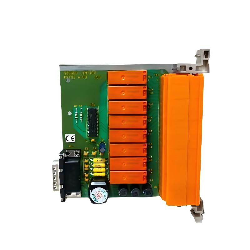
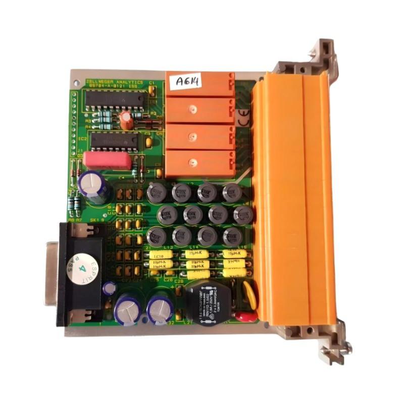
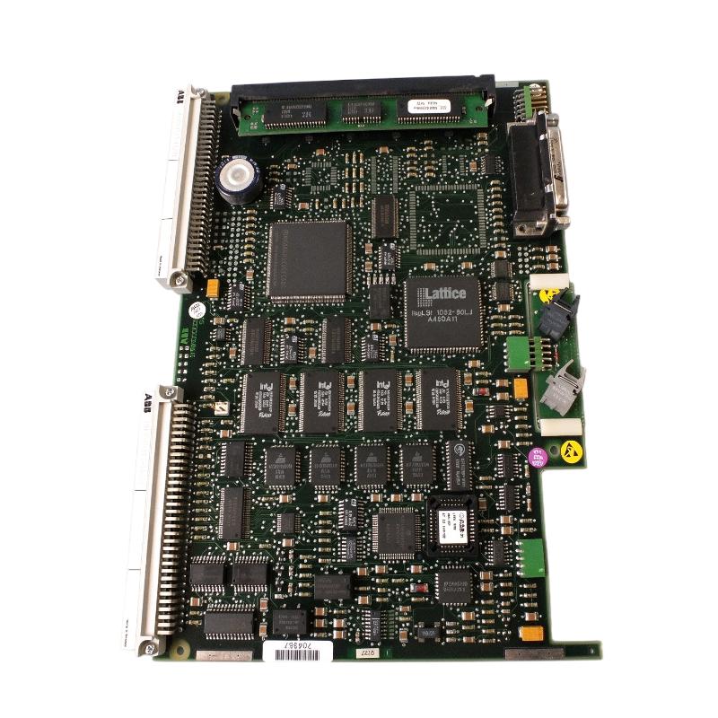
The 1MRK000167-ACr11 is an ABB printed circuit board belonging to the 1MRK000167 hardware family. It is intended for integration into compatible ABB industrial protection and control equipment.
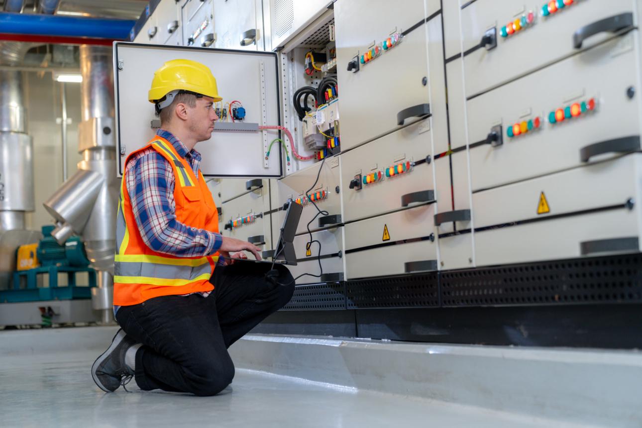
Because this PCB operates within a larger equipment architecture, effective Fault Diagnosis requires examining the complete hardware environment rather than focusing exclusively on the circuit board.
ABB 1MRK000167-ACr11 Fault Symptoms and Initial Assessment
Before attempting Repair, determine whether the failure is continuous, intermittent, or associated with a particular operating condition.
Typical symptoms requiring investigation include:
Equipment fails to complete its startup sequence.
Internal hardware recognition errors appear.
Communication between internal assemblies becomes unstable.
Equipment operation stops unexpectedly.
Diagnostic alarms appear after prolonged operation.
A replacement PCB is not accepted by the host equipment.
The fault returns after an apparently successful restart.
The timing of the failure is particularly important.
A hardware identification error immediately after replacement suggests a different investigation path from an intermittent reset occurring after several hours of operation.
Record the equipment alarm history before clearing diagnostic messages.
Fault Diagnosis of ABB 1MRK000167-ACr11 Startup Problems
A PCB-related startup problem does not automatically indicate damaged processing circuitry.
The startup sequence depends on several interconnected conditions, including auxiliary power, internal connections, hardware recognition, and the host equipment's initialization procedure.
The engineer should investigate these areas systematically.
Observation | Possible cause |
|---|---|
No normal startup response | Power supply or internal connection |
Hardware identification warning | Revision compatibility |
Initialization stops midway | Internal communication or configuration |
Repeated restart | Unstable supply or hardware fault |
Startup succeeds intermittently | Connector contact or temperature-related issue |
Start by checking the supply conditions specified in the host equipment documentation.
Next, inspect the board's mechanical installation and connector seating.
If both are satisfactory, review the equipment's diagnostic records and determine whether the failure is associated with hardware recognition, firmware compatibility, or another internal assembly.
Avoid replacing several components simultaneously because this makes it difficult to identify the original fault.
ABB 1MRK000167-ACr11 Intermittent Communication Fault Analysis
An intermittent internal communication fault can be particularly difficult to diagnose because the equipment may operate normally for extended periods.
Possible contributing factors include:
Poor connector contact.
Oxidized electrical interfaces.
Damaged internal communication wiring.
Unstable auxiliary power.
Electronic component deterioration.
Hardware or firmware incompatibility.
A useful investigation compares the communication alarm history with other equipment events.
For example, if communication failures occur at the same time as internal supply fluctuations, investigate the power distribution circuit before replacing the PCB.
If the supply remains stable, inspect the associated connectors and communication interfaces.
The objective is to establish whether the failure originates within the 1MRK000167-ACr11 itself or in another part of the host equipment.
PCB Physical Damage and Electronic Component Fault Diagnosis
Physical inspection can reveal evidence of an electrical or environmental failure.
Remove the board only after the equipment has been safely isolated and the applicable maintenance procedure has been followed.
Inspect the following areas:
Inspection area | Failure indicators |
|---|---|
Capacitors | Bulging, leakage, or damage |
Solder joints | Cracks or mechanical separation |
Connectors | Oxidation or damaged contacts |
PCB tracks | Burn marks or interrupted conductors |
Semiconductor components | Cracks or visible overheating |
Board surface | Corrosion or conductive contamination |
A thermal camera can also help identify abnormal heating when an approved energized diagnostic procedure is available.
However, visible damage is not required for an electronic failure to exist. Semiconductor degradation and intermittent solder connections may require specialist testing.
Investigating 1MRK000167-ACr11 Failures Related to Power Instability
Unstable power conditions can create symptoms that resemble internal PCB malfunction.
A board may repeatedly restart, fail to initialize, or produce intermittent diagnostic alarms when its supply voltage falls outside the permitted range.
The investigation should focus on the actual electrical supply requirements of the host equipment.
Check:
Auxiliary supply voltage.
Supply stability during startup.
Connector voltage drop.
Grounding and bonding arrangements.
Evidence of overheating around power connections.
Other equipment sharing the same supply circuit.
For example, a multimeter may indicate a normal voltage during standby while a brief voltage drop occurs during equipment initialization.
Where intermittent power disturbances are suspected, use an appropriately rated instrument capable of recording transient events.
Do not apply arbitrary test voltages directly to PCB terminals.
Hardware Revision and Configuration Errors on ABB 1MRK000167-ACr11
One important source of replacement-related problems is hardware revision incompatibility.
The 1MRK000167-ACr11 and 1MRK000167-ACr06 share the same base product number, but their suffixes identify different versions.
Their interchangeability must be established through the applicable ABB equipment documentation.
When a replacement board is not recognized, compare:
Complete PCB part number.
Hardware revision.
Host equipment model.
Supported firmware version.
Connector and mounting arrangement.
Required initialization procedure.
A configuration error should not be treated as proof of defective hardware.
If the replacement board is compatible, restore the required equipment parameters using the approved service procedure and repeat the hardware recognition test.
Practical Fault Isolation: Separating PCB Failure from External Problems
The most effective repair decisions come from comparing several independent observations.
Consider a protection and control assembly that develops an intermittent hardware alarm after operating normally for several hours.
The initial assumption might be that the newly installed PCB is defective.
However, an experienced engineer should first establish whether the fault follows temperature, supply conditions, or mechanical disturbance.
A practical diagnostic comparison is:
Test observation | Diagnostic conclusion |
|---|---|
Fault follows abnormal supply voltage | Investigate power distribution |
Fault changes after connector inspection | Investigate contact integrity |
Fault appears after firmware changes | Review software compatibility |
Fault persists with verified connections and supply | Investigate PCB hardware |
Fault follows the replacement board in a verified compatible test arrangement | Stronger evidence of PCB failure |
This approach avoids unnecessary component replacement and helps preserve the original fault evidence.
ABB 1MRK000167-ACr11 PCB Repair and Recovery Methods
The repair method should depend on the identified failure rather than the initial alarm description.
Identified fault | Corrective action |
|---|---|
Loose internal connection | Inspect and reseat the connector |
Oxidized contacts | Apply an approved contact-cleaning procedure |
Unstable auxiliary power | Repair the associated power supply circuit |
Incorrect replacement revision | Obtain the verified compatible board |
Configuration mismatch | Restore approved equipment parameters |
Damaged solder connection | Refer for qualified PCB repair |
Burned electronic components | Investigate the underlying electrical cause |
Persistent internal hardware failure | Replace the PCB with a compatible assembly |
Component-level repair should be performed only by qualified electronics specialists with suitable diagnostic equipment and circuit documentation.
For protection and control applications, an unverified PCB repair can create risks beyond the immediate hardware fault.
Post-Repair Validation and Commissioning of ABB 1MRK000167-ACr11
After repair or replacement, perform a complete equipment validation.
The maintenance engineer should verify:
Correct PCB identification.
Stable auxiliary power.
Proper connector seating.
Successful hardware recognition.
Normal startup and initialization.
Stable internal communication.
Completion of required self-diagnostics.
Correct operation of dependent equipment functions.
Where the board forms part of a protection system, perform the applicable functional and protection tests before returning the equipment to service.
The disappearance of an alarm is not sufficient proof that the original fault has been resolved.
Record the final diagnostic results and replacement details for future maintenance.
Preventing Recurring ABB 1MRK000167-ACr11 PCB Failures
Repeated PCB faults often require investigation beyond the board itself.
Review the operating environment and maintenance history for recurring electrical or mechanical stress.
Particular attention should be given to cabinet ventilation, temperature, humidity, contamination, grounding, auxiliary supply quality, and connector condition.
When replacing an electronic assembly, retain the complete part number and revision in the maintenance records. This is especially important when multiple versions of the ABB 1MRK000167 family are present in the same facility.
A consistent maintenance record helps engineers identify recurring failure patterns and make more accurate replacement decisions.
Long-Tail Keywords for ABB 1MRK000167-ACr11 Troubleshooting
ABB 1MRK000167-ACr11 troubleshooting guide
ABB 1MRK000167-ACr11 PCB fault diagnosis
ABB printed circuit board hardware failure
ABB 1MRK000167-ACr11 repair procedure
ABB processing board startup failure
ABB industrial PCB communication problems
ABB protection equipment hardware troubleshooting
ABB 1MRK000167-ACr11 replacement compatibility
ABB electronic circuit board diagnostics
ABB PCB intermittent hardware fault recovery