Allen Bradley 2080-L50E-48QVB Micro850 PLC Installation Guide (Wiring & Configuration)
Allen Bradley 2080-L50E-48QVB PLC Installation Overview
The Allen Bradley 2080-L50E-48QVB Micro850 PLC requires correct 24V DC power wiring, sinking-output circuit design, input signal configuration, and EtherNet/IP communication setup to ensure reliable machine control. One particularly important installation detail is that this controller uses 20 sinking DC outputs, which must be wired differently from sourcing-output versions such as the 2080-L50E-48QBB.
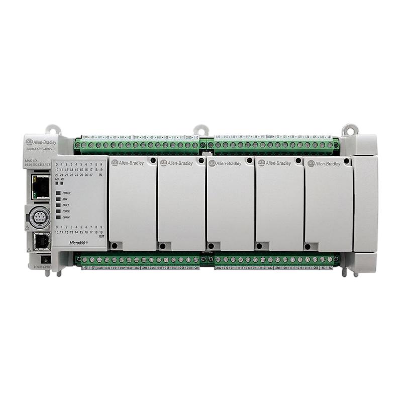
The 2080-L50E-48QVB is a 48-point Micro850 programmable controller featuring 28 digital inputs and 20 digital outputs. Its inputs support 24V DC/AC signals, while its outputs are 24V DC sinking type.
It is suitable for industrial applications involving machine sequencing, conveyor control, packaging equipment, material handling, and automated production systems.
The installation process should establish three things: stable controller power, correct field I/O operation, and reliable communication between the PLC and its engineering workstation.
Micro850 2080-L50E-48QVB Hardware Specifications
Before designing the control cabinet, verify the controller's electrical characteristics and installation requirements.
Parameter | Specification |
|---|---|
Manufacturer | Allen Bradley |
Model | 2080-L50E-48QVB |
Controller family | Micro850 |
Total I/O points | 48 |
Digital inputs | 28 |
Digital input type | 24V DC/AC |
Digital outputs | 20 |
Digital output type | 24V DC sinking |
Controller power supply | 24V DC |
Communication | Ethernet / EtherNet/IP |
Plug-in module slots | 5 |
Dimensions (H × W × D) | 90 × 238 × 80 mm |
Approximate weight | 0.725 kg |
The controller's output configuration is a major consideration when selecting field devices. A sinking output provides a current path toward the DC common, so the external load must be connected using the appropriate sourcing supply arrangement.
Installation Planning for the 2080-L50E-48QVB Micro850 Controller
A reliable Micro850 installation begins with an I/O allocation plan.
For a typical automated packaging machine, the 28 input points may be assigned to photoelectric sensors, proximity switches, push buttons, and equipment status contacts. The 20 output points can control suitable DC interface relays, indicator lamps, and other compatible loads.
Before mounting the controller, establish:
The available 24V DC control supply.
The expected input signal types.
The load current of each output circuit.
The required Ethernet network arrangement.
The number of additional plug-in or expansion modules.
Cabinet temperature and ventilation requirements.
The controller's maximum power consumption must also be considered when plug-in and expansion modules are installed. The base controller and the complete configured system should be evaluated separately.
Mounting and Electrical Preparation for Allen Bradley 2080-L50E-48QVB
Install the Micro850 controller inside a suitable industrial control enclosure, following the manufacturer's clearance and environmental requirements.
Before mounting, check the DIN rail or panel mounting surface for mechanical stability. Maintain sufficient clearance for terminal wiring, Ethernet cable routing, and heat dissipation.
The controller should not be installed immediately beside components that generate excessive heat unless the cabinet thermal design has been evaluated.
Use copper conductors with appropriate insulation ratings. The published terminal specifications allow solid or stranded conductors from 0.2 to 2.5 mm².
The specified terminal screw torque is 0.4–0.5 N·m.
Incorrect tightening can cause poor electrical contact, while excessive torque may damage the terminal assembly.
24V DC Power Supply Wiring and Verification
The 2080-L50E-48QVB requires a 24V DC controller power supply.
The specified operating range is 21.4–26.4V DC. Use a suitable regulated supply and verify that the available current capacity covers the controller and all connected accessories.
During installation, check:
Positive and negative supply polarity.
Power supply voltage under load.
Terminal tightness.
DC common distribution.
Protective grounding arrangements.
Separation between control and high-power wiring.
Do not confuse the controller's power input with its field I/O supply arrangements. The external supply design must account for the connected sensors and output loads as well as the PLC itself.
Wiring the 28 Digital Inputs on the Micro850 PLC
The 2080-L50E-48QVB provides 28 digital input points designed for 24V DC/AC signals.
Input wiring should follow the electrical requirements of the connected field devices and the controller's terminal diagram.
For DC sensor applications, verify whether the sensor is PNP or NPN and confirm that its output arrangement is compatible with the configured input circuit.
For example, a conveyor detection system may use PNP proximity sensors to report product presence and machine position.
Each sensor should be tested individually before the complete machine sequence is commissioned.
Avoid sharing signal commons incorrectly between unrelated circuits. Improper common wiring can create false input states or unexpected electrical interactions.
Sinking Output Wiring for Allen Bradley 2080-L50E-48QVB
The most important wiring distinction for this controller is its 20-point 24V DC sinking output arrangement.
A sinking output provides a current path toward 0V when activated. Therefore, the external load is normally connected between the positive 24V DC supply and the corresponding output terminal.
The basic circuit relationship is:
+24V DC → Field load → PLC sinking output → 0V DC
When the output transistor switches ON, current flows through the load and the output circuit.
When the output is OFF, the current path is interrupted.
For commissioning, verify the polarity of every connected load and confirm that the output current remains within the manufacturer's ratings.
The published output rating is up to 1A per point at 30°C surrounding air temperature, reducing to 0.3A per point at 65°C. Thermal derating and the applicable group or common limitations must also be checked.
For solenoid valves, contactors, and inductive loads, provide suitable suppression according to the load manufacturer's requirements.
Micro850 2080-L50E-48QVB System Configuration in Connected Components Workbench
The Micro850 controller is configured using Rockwell Automation's Connected Components Workbench (CCW).
After connecting the engineering workstation, create or open the correct controller project and select the 2080-L50E-48QVB hardware model.
The initial System Configuration should include:
Controller catalog number.
Firmware compatibility.
Digital input assignments.
Digital output assignments.
Ethernet network parameters.
Plug-in and expansion module configuration.
Application program settings.
Verify the controller identity before downloading a project.
Do not select the 2080-L50E-48QBB simply because the two models share the same Micro850 platform. The QBB has sourcing outputs, whereas the QVB has sinking outputs. Their field wiring arrangements are not interchangeable.
EtherNet/IP Communication Setup and PLC Programming
The 2080-L50E-48QVB supports Ethernet-based industrial communication.
Assign an IP address that matches the intended control network and does not conflict with another device.
For a machine network, document:
Network parameter | Configuration requirement |
|---|---|
IP address | Unique controller address |
Subnet mask | Match network design |
Gateway | Set according to network topology |
Device identification | Verify Micro850 controller |
Communication cable | Suitable industrial Ethernet cable |
Engineering software | Compatible CCW version |
After establishing communication, verify that the workstation can identify the controller and access its online status.
A simple PLC programming test can be used to verify an input-to-output relationship:
IF Conveyor_Sensor = ON
THEN Conveyor_Indicator = ON
ELSE Conveyor_Indicator = OFF
This is illustrative control logic. The actual output assignment must use a correctly wired sinking-output circuit.
Commissioning Tests for Allen Bradley 2080-L50E-48QVB
Commissioning should proceed from electrical verification to individual I/O testing and finally to machine sequence validation.
Test | Expected result |
|---|---|
24V DC supply | Within specified operating range |
Controller startup | Normal status |
Input activation | Correct input status change |
Output activation | Corresponding load operates |
Ethernet connection | Stable online communication |
Program execution | Correct sequence behavior |
Inductive loads | No abnormal switching interference |
Field commissioning scenario:
During a packaging-machine startup, the Micro850 controller communicates correctly with the engineering workstation, and all sensor inputs respond as expected. However, several solenoid valves fail to operate when their PLC outputs are activated.
The engineer should first check the output wiring topology. If the loads have been wired as though the controller uses sourcing outputs, the current path will be incorrect.
After confirming the sinking-output arrangement, the engineer verifies the 24V supply, output common connections, and load current before repeating the functional test.
This type of wiring mismatch is a more logical initial investigation than immediately replacing a new controller.
Long-Tail Keywords for 2080-L50E-48QVB Installation
Allen Bradley 2080-L50E-48QVB installation guide
Micro850 2080-L50E-48QVB wiring diagram
Allen Bradley Micro850 48 I/O PLC setup
2080-L50E-48QVB sinking output wiring
Micro850 PLC Connected Components Workbench configuration
Allen Bradley 2080-L50E-48QVB commissioning
Micro850 EtherNet/IP communication setup
2080-L50E-48QVB digital input and output configuration