Allen Bradley 2080-L50E-48QVB Micro850 PLC Output Fault Troubleshooting Guide (Sinking Output Diagnosis)
Diagnosing Allen Bradley 2080-L50E-48QVB Output Failures
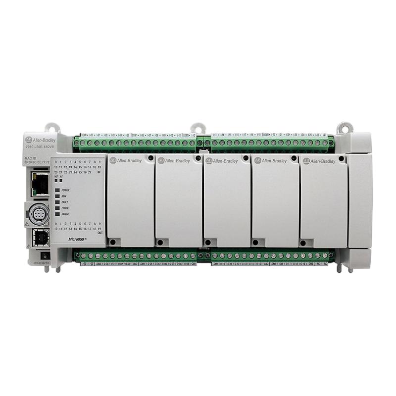
Allen Bradley 2080-L50E-48QVB output failures are often related to incorrect sinking-output wiring, overloaded field circuits, missing DC common connections, or damaged output transistors. When a Micro850 PLC executes its program correctly but connected solenoid valves, relays, or indicator lamps fail to operate, the output circuit should be investigated before replacing the controller.
The 2080-L50E-48QVB is a 48-point Micro850 controller with 28 digital inputs and 20 24V DC sinking outputs. Its output architecture is different from the sourcing-output 2080-L50E-48QBB, making wiring compatibility an important part of Fault Diagnosis.
This Troubleshooting Guide focuses on output switching failures, electrical loading, field wiring, and controller diagnostics.
Recognizing 2080-L50E-48QVB Digital Output Fault Symptoms
Output problems can appear in several ways during machine operation.
Common symptoms include:
PLC output status changes, but the connected device does not operate.
Solenoid valves respond intermittently.
Several output channels fail simultaneously.
Output devices remain inactive after program execution.
Output circuits operate during manual testing but fail under normal load.
The controller reports unexpected hardware or I/O-related faults.
Output behavior changes after prolonged machine operation.
The first diagnostic distinction is whether the PLC program is actually commanding the output.
An inactive field device does not necessarily indicate a defective output transistor.
Why Micro850 Sinking Outputs Fail to Activate Field Loads
The 2080-L50E-48QVB uses sinking transistor outputs.
In a correctly wired circuit, the load receives positive 24V DC on one side, while the PLC output provides the switching path toward 0V DC.
A typical arrangement is:
+24V DC → Solenoid coil → PLC output → 0V DC
If the load is wired according to a sourcing-output arrangement, the circuit may not operate as expected.
This is particularly important when replacing another Micro850 model.
For example, the 2080-L50E-48QBB uses sourcing outputs, whereas the 2080-L50E-48QVB uses sinking outputs. Transferring the original wiring without checking the output architecture can create commissioning problems.
Before performing hardware Fault Diagnosis, compare the actual terminal connections with the controller's electrical documentation.
Fault Investigation: PLC Output Status Is ON but the Solenoid Does Not Operate
This is one of the most useful troubleshooting scenarios for a Micro850 controller.
Assume that an automated machine commands a pneumatic valve through output channel 4. The PLC program executes normally, but the valve does not energize.
The engineer should investigate the circuit in the following order:
Diagnostic check | What to investigate |
|---|---|
PLC logic | Is the output command active? |
Output status | Does the corresponding output change state? |
Field supply | Is 24V DC available? |
Output common | Is the correct 0V reference connected? |
Solenoid coil | Is the coil electrically intact? |
Wiring | Are the load and output terminals connected correctly? |
Output circuit | Can the channel switch under the intended load? |
Measure the voltage across the solenoid coil rather than relying exclusively on the PLC program status.
If the output command is active but the coil receives no effective voltage, investigate the external current path.
Field case scenario:
During commissioning of a conveyor system, several pneumatic valves fail to energize even though the corresponding output bits change correctly in the Micro850 program.
The initial assumption is that the output channels are damaged.
However, inspection reveals that the field loads were wired using a sourcing-output arrangement. The controller's sinking-output configuration was overlooked during the electrical design.
Correcting the wiring arrangement and verifying the output common restores the intended switching operation.
This illustrates why output topology should be checked before ordering a replacement PLC.
Diagnosing Overloaded 2080-L50E-48QVB Output Circuits
An output circuit can operate correctly without a load but fail when connected to an actual device.
This often indicates an electrical loading problem.
The 2080-L50E-48QVB supports a maximum output rating of 1A per point at 30°C surrounding air temperature. At 65°C, the published rating decreases to 0.3A per point.
Consequently, an output that works during a cool commissioning test may behave differently inside a hot control cabinet.
Check the following:
Actual load current.
Solenoid coil resistance.
Output group loading.
Cabinet temperature.
Inductive switching characteristics.
Applicable manufacturer derating requirements.
Do not evaluate output capacity using only the rated current printed on an external device. Consider its operating and switching characteristics.
For larger loads, an appropriately rated interposing relay or external switching device may be required.
Micro850 Output Troubleshooting When Multiple Channels Stop Working
When several outputs fail at the same time, investigate shared electrical conditions before assuming multiple output transistors have failed simultaneously.
Potential causes include:
Loss of the external 24V DC field supply.
Incorrect output common wiring.
Excessive load current.
Common wiring damage.
Electrical disturbances from inductive loads.
Incorrect system wiring following maintenance.
A useful diagnostic technique is to compare affected and unaffected channels.
If one output operates normally while several others remain inactive, compare their supply distribution and common connections.
If all outputs in an affected group fail together, investigate shared circuit conditions and the applicable protection arrangements.
This method reduces unnecessary replacement of individual output devices.
Electrical Noise and Inductive Load Protection
The Micro850 controller may operate in environments containing contactors, motors, solenoids, and variable-frequency drives.
These devices can generate electrical disturbances when switched.
Inductive loads are particularly important because their stored energy can generate voltage transients when the output circuit is interrupted.
For troubleshooting, inspect:
Suppression devices across DC coils.
Cable routing near motor power conductors.
Output wiring insulation.
Common-terminal connections.
Evidence of abnormal heating.
Repeated output switching under operating conditions.
Use suitable suppression devices according to the load manufacturer's recommendations.
Do not install an arbitrary suppression component without checking its voltage rating, polarity, and compatibility with the switching circuit.
Separating PLC Logic Errors from 2080-L50E-48QVB Hardware Faults
A Micro850 output may remain inactive because the program never reaches the instruction that controls it.
For this reason, inspect the complete logic conditions before testing the output hardware.
Consider the following illustrative control logic:
IF Start_Command = ON
AND Safety_Permit = ON
AND Motor_Ready = ON
THEN Conveyor_Output = ON
If Safety_Permit remains OFF, the conveyor output will not activate even when the start command is present.
In Connected Components Workbench, monitor the relevant variables and output commands online.
Check:
Input conditions.
Interlocks.
Timers and counters.
Program execution order.
Output assignments.
Force or override conditions.
If the internal command remains OFF, investigate the application program rather than replacing the output hardware.
EtherNet/IP and Micro850 Communication Fault Diagnosis
The 2080-L50E-48QVB also supports Ethernet-based communication.
Communication problems may affect HMI monitoring, remote control commands, and data exchange with other automation devices.
Typical symptoms include:
HMI values stop updating.
Controller communication becomes intermittent.
Remote commands are not received.
Engineering software loses online access.
Network devices cannot consistently identify the controller.
Check the IP address, subnet configuration, Ethernet cable condition, switch ports, and network addressing.
A duplicate IP address can create communication problems even when the PLC itself remains operational.
If local I/O operates normally while remote commands fail, investigate the Ethernet network before diagnosing a controller hardware defect.
Micro850 Hardware Fault Diagnosis and Recovery
After external wiring, load conditions, and application logic have been verified, the investigation can move toward possible internal controller damage.
A suspected output transistor failure should be evaluated using a controlled test with an appropriate 24V DC supply and a known-good compatible load.
The test must follow the manufacturer's electrical specifications and applicable safety procedures.
Identified problem | Recommended corrective action |
|---|---|
Incorrect sinking-output wiring | Correct the load current path |
Missing 24V DC supply | Restore the field supply |
Incorrect output common | Correct common connections |
Excessive load current | Reduce or redistribute loading |
Defective solenoid | Repair or replace the field device |
Electrical switching disturbance | Improve load suppression |
Incorrect PLC logic | Correct program conditions |
Ethernet communication failure | Repair network configuration or wiring |
Suspected damaged output channel | Perform controlled hardware evaluation |
If an internal output channel has failed, replacement may be necessary. Before installing another controller, identify the original electrical cause to prevent repeated damage.
Post-Repair Testing of Allen Bradley 2080-L50E-48QVB
After completing repairs, perform a channel-by-channel validation.
Start with the controller's power supply and input circuits. Then test each output individually using the intended load.
For production equipment, include testing under normal operating temperature and representative switching conditions.
The final validation should confirm:
Stable 24V DC supply.
Correct sinking-output polarity.
Normal input response.
Correct output switching.
Acceptable output current.
Stable EtherNet/IP communication.
Correct program execution.
No recurring controller diagnostics.
Document any replaced components, wiring modifications, and measured electrical values.
Preventing Recurring Micro850 2080-L50E-48QVB Output Problems
Preventive maintenance should focus on output loading, cabinet temperature, field wiring, and electrical interference.
Inspect terminal connections periodically and verify that connected loads remain within the controller's operating limits.
When modifying a machine, update the I/O drawings and output assignment records. This is especially important when replacing sourcing-output controllers with sinking-output versions.
A clear distinction between the 2080-L50E-48QVB and 2080-L50E-48QBB helps prevent wiring errors during future maintenance.
Long-Tail Keywords for 2080-L50E-48QVB Troubleshooting
Allen Bradley 2080-L50E-48QVB troubleshooting guide
Micro850 2080-L50E-48QVB output fault diagnosis
Allen Bradley Micro850 sinking output problems
2080-L50E-48QVB digital output not working
Micro850 PLC solenoid output troubleshooting
Allen Bradley 2080-L50E-48QVB output wiring
Micro850 PLC Ethernet communication fault
2080-L50E-48QVB hardware failure diagnosis
Allen Bradley Micro850 output transistor failure
Micro850 PLC repair and commissioning