Allen Bradley 2080-L50E-48QBB Micro850 PLC Installation Guide (Wiring, Configuration & Commissioning)
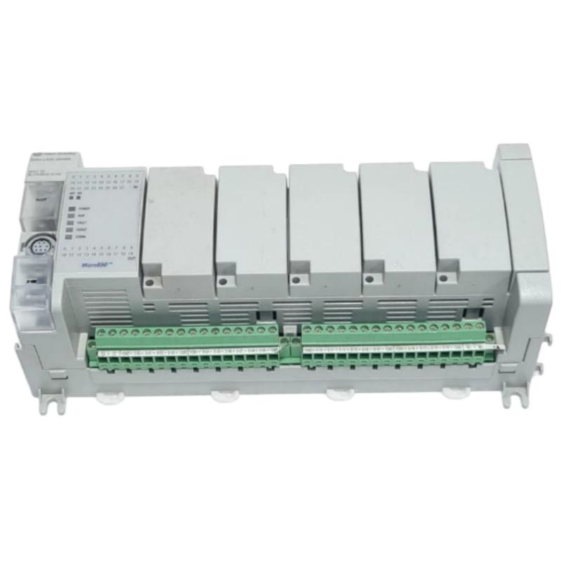
The Allen Bradley 2080-L50E-48QBB Micro850 Programmable Controller is a 48-point PLC designed for machine automation and distributed control applications. It provides 28 digital inputs and 20 transistor outputs, with 24V DC sourcing output technology and EtherNet/IP communication. Correct installation depends on matching the output wiring to the sourcing configuration, providing a stable 24V DC supply, and validating the controller program before connecting field loads.
1. Understanding the 2080-L50E-48QBB Hardware
Before installing the Micro850 PLC, confirm the complete catalog number on the controller label. The suffix is important because Micro850 models with similar appearances can have different output circuits.
Key hardware characteristics include:
Parameter | Specification |
|---|---|
Controller family | Allen Bradley Micro850 |
Catalog number | 2080-L50E-48QBB |
Total I/O points | 48 |
Digital inputs | 28, 24V DC/AC |
Digital outputs | 20, 24V DC sourcing |
Communication | EtherNet/IP |
Power supply | 24V DC |
Plug-in module slots | Up to 5 |
The 48QBB version uses sourcing transistor outputs. This is an important distinction from the 2080-L50E-48QVB, which uses sinking outputs. The two versions should not be treated as interchangeable when designing field wiring.
2. Preparing the Micro850 PLC for Installation
A reliable installation starts with checking the control cabinet and connected equipment.
Before mounting the controller:
Confirm that the cabinet provides sufficient space for wiring, ventilation, and maintenance access.
Check that the 24V DC power supply can support the controller and connected system loads.
Inspect the controller terminals, Ethernet port, and plug-in module slots for physical damage.
Separate low-level signal wiring from motor cables and other high-interference conductors.
Verify that the selected sensors and actuators are electrically compatible with the controller's I/O configuration.
The controller's published supply voltage range is 21.4–26.4V DC. Use a regulated supply within this range and check the voltage at the controller terminals under operating conditions.
3. Mounting and Electrical Wiring of the 2080-L50E-48QBB
The Micro850 controller can be installed on a suitable DIN rail or mounted according to the manufacturer's mechanical instructions. Ensure that the mounting surface is stable and that the controller is not exposed to excessive vibration, moisture, or conductive contamination.
3.1 Power Supply Connections
Connect a regulated 24V DC supply to the designated controller power terminals. Verify polarity before energizing the system.
A voltage drop caused by undersized conductors, loose terminals, or an overloaded supply can lead to intermittent controller operation. Measure the voltage at the PLC rather than relying only on the power supply's front-panel display.
3.2 Digital Input Wiring
The controller provides 28 digital inputs supporting 24V DC/AC input configurations. When using DC sensors, check the sensor output type and the input circuit requirements before connecting the signal wires.
For each input point:
Identify the correct input terminal and common connection.
Confirm the sensor's rated operating voltage.
Check the polarity and signal reference.
Test the input status using the controller indicators or programming software.
Do not assume that every sensor with a 24V rating can be wired identically. PNP/NPN output behavior and the input circuit configuration must be considered.
3.3 Sourcing Output Wiring
The 20 digital outputs on the 2080-L50E-48QBB are 24V DC sourcing outputs. When an output turns on, it supplies positive voltage to the connected load.
A typical sourcing-output circuit uses the PLC output to deliver +24V DC to the load, with the other side of the load connected to the appropriate 0V reference.
Check the load current, wiring size, protective devices, and output-group arrangement before commissioning. The published standard output rating is temperature-dependent: up to 1.0A per point at 30°C, decreasing to 0.3A per point at 65°C. These figures should not be interpreted as permission to operate every output at its maximum rating simultaneously under all cabinet conditions.
4. Micro850 PLC Programming and Ethernet Configuration
The 2080-L50E-48QBB is configured using Rockwell Automation's Connected Components Workbench (CCW) software.
A practical configuration sequence is:
Create the controller project
Select the correct Micro850 controller catalog number in the software. Confirm that the project hardware matches the physical unit installed in the cabinet.
Configure I/O and plug-in modules
Review the input and output assignments. If additional plug-in modules are installed, verify their configuration and channel settings before downloading the project.
Establish Ethernet communication
Connect the controller to the engineering computer through the Ethernet port. Configure the IP address and subnet settings according to the plant network plan. Avoid duplicate IP addresses on the same network.
Develop and validate the control logic
Create the required program routines and verify the I/O mapping. Test interlocks, startup conditions, output permissives, and fault-handling logic before connecting machinery for automatic operation.
Download and monitor
Download the validated project to the controller. Monitor input states, output commands, and communication status to confirm that the program behaves as expected.
5. Commissioning Checks Before Production
A controller that powers up successfully is not necessarily ready for machine operation. Commissioning should verify the complete signal path from the field device to the PLC program and back to the actuator.
Inspection item | Acceptance check |
|---|---|
Supply voltage | Stable and within the specified range |
Input signals | Correct status changes when sensors operate |
Output wiring | Compatible with sourcing output configuration |
Output loads | Within applicable current and temperature limits |
Ethernet connection | Correct IP settings and stable communication |
PLC program | No unresolved configuration or logic errors |
Safety interlocks | Tested independently according to the machine design |
For the first output test, disconnect or isolate the actual actuator where practical and use a suitable test load. This helps identify wiring mistakes before a motor, valve, or other machine component is energized.
6. Common Installation Mistakes to Avoid
Several commissioning problems can be traced to small configuration or wiring errors.
Using sinking-output wiring: The 48QBB is a sourcing-output model. Wiring designed for the 48QVB may prevent the load from operating correctly.
Ignoring output derating: Output current capability decreases as the surrounding air temperature increases.
Selecting the wrong controller in CCW: A catalog-number mismatch can result in incorrect I/O assumptions.
Overlooking Ethernet addressing: Duplicate IP addresses can cause intermittent or complete communication loss.
Skipping load testing: An output indicator alone does not confirm that the connected actuator receives the correct voltage and current.
7. Installation and Commissioning FAQs for Allen Bradley 2080-L50E-48QBB
Q1: How many I/O points does the 2080-L50E-48QBB provide?
It provides 48 built-in I/O points, consisting of 28 digital inputs and 20 digital outputs.
Q2: Are the digital outputs on the 2080-L50E-48QBB sourcing or sinking?
They are 24V DC sourcing transistor outputs. The output wiring must be designed for this circuit type.
Q3: Can the 2080-L50E-48QBB communicate through EtherNet/IP?
Yes. The controller supports EtherNet/IP communication through its Ethernet interface.
Q4: Which software is used to program the Micro850 controller?
Connected Components Workbench (CCW) is used to configure, program, download, and monitor the controller.
Q5: Can the 2080-L50E-48QBB accept 24V DC sensor signals?
Yes, its digital inputs support 24V DC/AC configurations. The sensor's output type and wiring arrangement must still be checked.
Q6: How many plug-in modules can be installed?
The controller supports up to five plug-in module slots, subject to module compatibility and system configuration requirements.
Q7: What should be checked if an input does not turn on?
Check the sensor supply, signal polarity, input common connection, terminal wiring, and input status indicator.
Q8: Can the 2080-L50E-48QBB directly drive a contactor coil?
It may be suitable for compatible DC loads within the output ratings, but the coil's current and inductive characteristics must be checked. Appropriate suppression and interposing devices may be required.
Q9: What is the controller's required power supply?
It uses a 24V DC supply. The published operating voltage range is 21.4–26.4V DC.
Q10: Why should the 48QBB and 48QVB models be checked carefully before replacement?
Their transistor output configurations differ: the 48QBB uses sourcing outputs, while the 48QVB uses sinking outputs. Replacing one with the other without reviewing the field wiring can cause output malfunction.