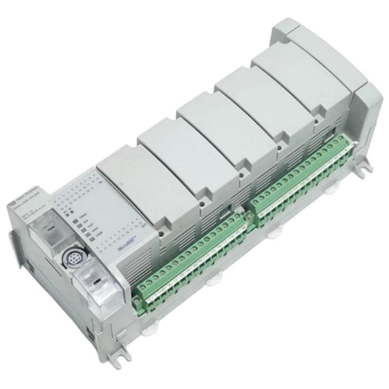
The Allen Bradley 2080-L50E-48QBB Micro850 Programmable Controller is a 48-point PLC designed for machine automation and distributed control applications. It provides 28 digital inputs and 20 transistor outputs, with 24V DC sourcing output technology and EtherNet/IP communication. Correct installation depends on matching the output wiring to the sourcing configuration, providing a stable 24V DC supply, and validating the controller program before connecting field loads. 1. Understanding the 2080-L50E-48QBB Hardware Before installing the Micro850 PLC, confirm the complete catalog number on the
When an Allen Bradley 2080-L50E-48QBB Micro850 PLC shows an output command in the program but the connected actuator does not operate, the problem may involve the output circuit, load wiring, power supply, or program logic. One particularly important diagnostic point is that this controller uses 24V DC sourcing outputs. Checking the output's electrical path before replacing the PLC can prevent unnecessary hardware changes.
1. Recognizing Digital Output Problems on the 2080-L50E-48QBB
Output-related faults can appear in several ways:
The PLC program activates an output, but the actuator remains inactive.
An output indicator changes state, but the field device does not respond.
A connected load operates intermittently.
The output works during a low-load test but fails under normal operating conditions.
Several output points stop working after a wiring or power-supply change.
These symptoms do not automatically indicate a defective controller. A fault may exist in the load, external power circuit, common wiring, or control logic.
2. Fault Diagnosis: Output Command Is Active but the Load Does Not Operate
This is a useful starting point for troubleshooting the 2080-L50E-48QBB because it separates software problems from electrical problems.
Check the PLC Program State
Open the project in Connected Components Workbench and monitor the relevant output variable.
Confirm that:
The output command is actually being executed.
No interlock or permissive condition is preventing activation.
The output address corresponds to the physical terminal being tested.
The program is running in the expected operating mode.
If the logic never commands the output, investigating the transistor circuit will not solve the problem.
Verify the Sourcing Output Circuit
The 2080-L50E-48QBB supplies positive voltage from an activated output. Check whether the load is wired to receive this voltage and whether its return connection is correct.
A common mistake is using a wiring arrangement intended for a sinking-output PLC. This can leave the load without a complete current path even when the PLC program is operating normally.
Measure the voltage at the output terminal relative to the appropriate reference point, then measure across the load. Use the controller's wiring documentation to identify the correct terminals and reference connections.
Inspect the Load and Field Wiring
Disconnect power before tightening terminals or changing wiring. Check for:
Loose terminal screws.
Broken conductors.
Incorrect load polarity.
Damaged connectors.
Blown external fuses.
Short circuits or excessive load current.
If the output voltage is present but the actuator does not operate, test the load independently using an appropriate, protected power source.
3. Output Overload and Temperature-Related Faults
The transistor output circuit has operating limits that must be considered during troubleshooting.
The published standard output rating is up to 1.0A per point at 30°C, with a reduced rating of 0.3A per point at 65°C. Actual application limits also depend on the applicable output configuration and installation conditions.
A load that operates normally in a cool test environment may become unreliable inside a hot electrical cabinet.
Investigate the following:
Measure the load's steady-state current.
Check the inrush current when the actuator starts.
Inspect the cabinet temperature and ventilation.
Check whether multiple outputs are driving high-current loads.
Compare the measured load conditions with the controller's technical specifications.
If the load exceeds the permitted output conditions, use an appropriately rated interposing relay or driver rather than relying on the PLC output to handle the excessive current.
4. Intermittent Output Operation During Machine Running
Intermittent operation can be more difficult to diagnose than a completely inactive output because the fault may only appear under specific operating conditions.
Possible causes include:
Unstable 24V DC supply
A supply voltage that drops during actuator startup can affect the controller or field circuit. Measure the voltage while the machine is operating, especially when several loads switch simultaneously.
Electrical interference
Motor drives, contactors, and switching power devices can introduce electrical noise. Review cable routing, grounding, shielding, and suppression arrangements.
Loose connections
Vibration may cause a terminal or connector to lose contact intermittently. Inspect the wiring and terminal condition while the equipment is safely isolated.
Load deterioration
A damaged solenoid, relay coil, or other actuator may draw abnormal current or behave inconsistently. Test the field device separately.
Record the conditions under which the fault occurs, including machine cycle, load state, cabinet temperature, and controller status. This information helps narrow down the cause.
5. Micro850 Ethernet Communication and Program-Related Checks
Not every apparent output fault originates in the output hardware. A communication interruption or program-state issue may prevent the intended command from reaching the physical output logic.
For the 2080-L50E-48QBB, check the following:
Diagnostic area | What to examine |
|---|---|
Controller mode | Confirm the controller is in the expected operating mode |
Program execution | Check whether the relevant routine is executing |
I/O mapping | Confirm the software address matches the physical output |
Ethernet network | Review IP configuration and communication status |
Remote commands | Check whether external devices are supplying the expected control data |
Interlocks | Verify that permissives and fault conditions are satisfied |
If the output is controlled by data received from another device, monitor the communication data and confirm that the value remains valid when the fault occurs.
6. A Practical Isolation Method for Output Faults
A controlled test can help determine whether the problem is in the PLC, wiring, or load.
Place the machine in a safe state and isolate hazardous energy sources as required.
Identify the affected output point and verify its program address.
Disconnect the field load where appropriate and permitted by the machine design.
Inspect the output wiring and confirm that it matches the sourcing configuration.
Use a suitable test load within the specified output ratings.
Command the output through an approved test procedure.
Measure the output voltage and compare it with the expected behavior.
Reconnect the original load only after confirming that the circuit is correctly wired and protected.
If a compatible test load operates normally but the original actuator does not, investigate the field device and its wiring. If the output fails with a correctly configured test circuit, continue checking the supply, terminal connections, output protection requirements, and controller hardware.
Never force outputs or bypass machine safety interlocks simply to make a test easier.
7. When Should the 2080-L50E-48QBB Be Replaced?
Controller replacement should be considered only after external causes have been eliminated.
Replacement may be justified when:
A specific output point repeatedly fails under verified normal operating conditions.
Physical damage is visible on the terminal or controller housing.
The controller cannot maintain normal operation despite a verified power supply and correct configuration.
A known-good compatible load and wiring arrangement produce the same hardware-related failure.
Before installing a replacement, record the existing controller catalog number, series, firmware information, program version, Ethernet settings, and plug-in module configuration.
A replacement must also be checked for output type. In particular, do not substitute a sinking-output 2080-L50E-48QVB for the sourcing-output 2080-L50E-48QBB without reviewing the complete electrical design.
8. Troubleshooting FAQs for Allen Bradley 2080-L50E-48QBB
Q1: Why does the 2080-L50E-48QBB output indicator turn on but the actuator does not move?
Possible causes include incorrect sourcing-output wiring, a missing load return connection, an open fuse, a damaged actuator, or excessive load current. Measure the voltage across the load and inspect the complete current path.
Q2: Can incorrect output wiring damage a Micro850 controller?
Incorrect wiring can cause malfunction and may damage the output circuit, depending on the fault conditions. Always verify polarity, terminal assignments, load current, and protection before energizing the system.
Q3: Why does an output work with a small test load but fail with the actual actuator?
The actual actuator may have excessive steady-state or inrush current. Check its electrical ratings and compare them with the controller's output limits.
Q4: Why do several outputs fail at the same time?
Check the common power supply, wiring references, external fuses, and program conditions first. Multiple simultaneous failures do not necessarily mean that several output transistors have failed.
Q5: Can a 48QBB replace a 48QVB directly?
Not necessarily. The 48QBB has sourcing outputs, while the 48QVB has sinking outputs. Review the existing field wiring and load circuit before considering a replacement.
Q6: What causes intermittent PLC output operation?
Common causes include unstable supply voltage, loose terminals, electrical interference, excessive load current, and deteriorating field devices.
Q7: How can I determine whether an output fault is caused by the program?
Monitor the output variable and the relevant interlock conditions in Connected Components Workbench. If the program does not issue the command, investigate the logic and input conditions before testing the output hardware.
Q8: Does high cabinet temperature affect Micro850 transistor outputs?
Yes. The published standard output rating decreases from 1.0A per point at 30°C to 0.3A per point at 65°C. Thermal conditions should be considered when investigating load-related problems.
Q9: Can electrical noise cause false output behavior?
Electrical interference can affect control-system signals and connected equipment. Check cable separation, grounding, shielding, and suitable suppression for inductive loads.
Q10: What information should be recorded before replacing a faulty controller?
Record the full catalog number, controller series, firmware version, project backup, Ethernet settings, I/O wiring, plug-in modules, and the symptoms observed during testing. This makes replacement and recommissioning more reliable.