Honeywell 10001/A/1 Vertical Bus Driver (VBD) Installation Guide for FSC Control System
Honeywell 10001/A/1 vertical bus driver wiring errors are most often caused by incorrect jumper configuration, improper rack grounding, or faulty backplane contact pressure, rather than failure of the electronic module itself. In FSC (Fail Safe Control) systems, the vertical bus is the backbone of communication between the central processor and I/O racks, so even minor wiring deviations can disrupt the entire control chain.
Honeywell 10001/A/1 Role in Vertical Bus Architecture
The Honeywell 10001/A/1 is the wiring and interface part of the Vertical Bus Driver (VBD) module, used in FSC systems to connect:
- Central Processor (CP) rack
- Vertical bus flat cable
- Horizontal Bus Drivers (HBDs) in I/O racks
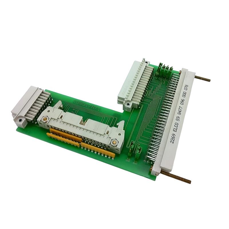
The complete VBD module (10001/1/1 or 10001/R/1) consists of:
- Electronic mainboard
- Wiring/interface unit: 10001/A/1
The 10001/A/1 part is mechanically fixed using a 96-pin connector and bolt system, allowing replacement of the electronic board without disconnecting the vertical bus cable.
In one chemical plant modernization project, intermittent I/O dropouts were traced to a slightly loosened 10001/A/1 connector bolt. Tightening restored full bus communication immediately.
Honeywell 10001/A/1 Installation Preparation
Before installing or servicing the module, engineers must verify system-level stability:
Rack Conditions
- Central Part rack securely grounded
- No vibration from adjacent rotating machinery
- Proper spacing between VBD modules (heat dissipation required)
Electrical Preconditions
- Stable 5 V DC supply on backplane
- Ripple within acceptable range (<50 mV p-p)
- No shared grounding loops with high-current drives
Field experience shows that unstable grounding in FSC cabinets often leads to intermittent bus synchronization loss, especially during motor startup.
Honeywell 10001/A/1 Jumper Configuration (Critical Step)
The wiring part includes configuration jumpers:
J1–J4
- Define VBD number (module address)
- Must be unique within Central Part rack
J5–J6
- Define Central Processor (CP) number
- Required for redundant system mapping
Field Observation
In one refinery, two VBD modules were accidentally configured with the same VBD number. This caused intermittent I/O mapping conflicts, leading to random input channel “flicker” every few minutes. After correcting jumper settings, system stabilized instantly.
Mechanical Installation and Bus Connection
Step-by-Step Field Practice
- Align 10001/A/1 to rack mounting surface
- Secure using bolt torque on 96-pin connector
- Ensure flat cable is not twisted or under tension
- Confirm full seating before powering system
Critical Failure Mode
Partial tightening of the 96-pin connector can cause:
- Intermittent I/O loss
- Random channel resets
- Bus synchronization failure
In one LNG facility, vibration loosened the connector over time, causing repeated I/O rack dropout every 20–30 minutes until mechanical re-tightening was performed.
Vertical Bus Communication Behavior
The vertical bus connects:
- Central rack (VBD) → I/O racks (HBDs)
Key characteristics:
- Distance limit: up to 5 meters
- Each VBD supports up to 10 HBD modules
- Up to 14 VBD modules per Central Processor
During commissioning, engineers often observe that signal instability appears only under load, which is typically caused by:
- Bus cable impedance mismatch
- Ground potential differences between racks
- Poor shielding of flat cables
After correcting grounding in one offshore installation, bus error rate dropped from intermittent faults to zero over 72 hours of continuous monitoring.
Commissioning Strategy (Field-Oriented)
Cold Start Validation
- Verify CP boot sequence completion
- Confirm all VBD modules recognized
- Check LED status consistency
Load Test
- Activate multiple I/O racks simultaneously
- Monitor bus latency and synchronization stability
- Check for channel mapping errors
Stress Test
- Simulate high-load process conditions
- Observe bus stability during motor startup
- Validate redundancy switching (if applicable)
In one petrochemical plant, bus instability appeared only when compressors started. Root cause was shared grounding between motor power and FSC rack system.