Bently Nevada 3500/15-03-03-00 Power Supply Module Installation Guide (3500 Series Rack Power Setup & Commissioning)
Bently Nevada 3500/15-03-03-00 Power Module Role in 3500 System Architecture
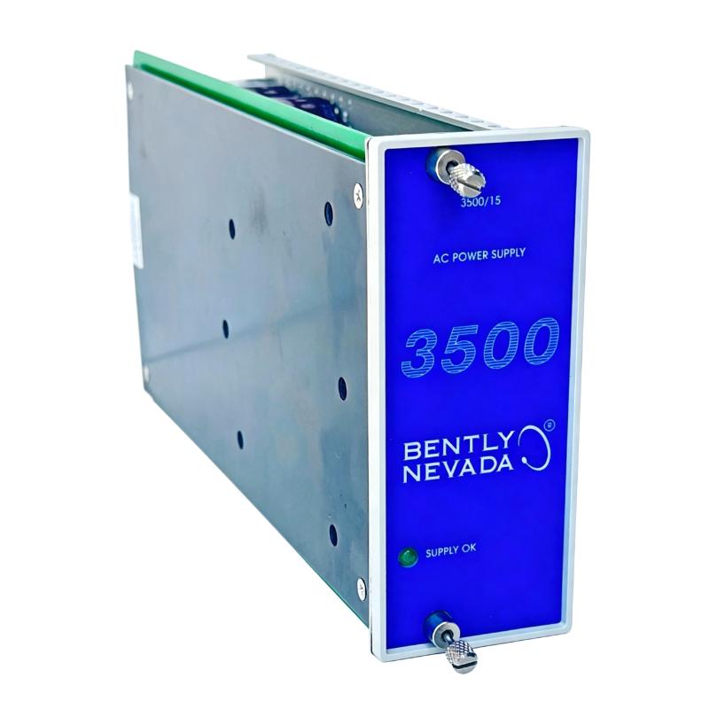
The Bently Nevada 3500/15-03-03-00 is a high-voltage dual-input power supply module designed for the 3500 machinery protection system rack. It typically supports:
- High voltage DC input (88–140 VDC)
- High voltage AC input (up to 175–264 VAC depending configuration)
- Dual redundant power operation within 3500 rack architecture
In one gas turbine monitoring cabinet we worked on, the module was powering a full rack including vibration, keyphasor, and relay modules. Any instability in this unit immediately triggered rack-wide “system voltage low” alarms.
Bently Nevada 3500/15 Installation Preparation & Engineering Checks
Before inserting the module into a live rack, field engineers typically verify:
- Correct slot assignment (Power Supply slot in 3500/05 rack)
- Input voltage compatibility (AC vs DC configuration mismatch is critical risk)
- Backplane connector cleanliness (oxidation or dust can cause intermittent boot faults)
- Ground integrity of rack frame (<1Ω preferred in industrial practice)
In one commissioning case at a petrochemical site, a technician installed the correct module but in a slightly misaligned slot. The system powered intermittently, producing unstable diagnostics across all vibration channels.
Bently Nevada 3500/15 Installation Procedure (Field Practice)
Unlike generic PLC modules, the 3500 power module requires precise mechanical insertion due to backplane high-current contacts.
Typical installation flow used in field commissioning:
- Verify rack power isolation before insertion
- Align module rails with rack guide slots carefully
- Insert steadily until backplane connector fully engages (no partial seating allowed)
- Lock module handle to ensure full electrical contact pressure
- Restore input power and monitor LED status sequence
In one real turbine shutdown case, a partially seated module caused repeated “rack reset cycling” every few seconds until the mechanical lock was fully engaged.
Bently Nevada 3500/15 Commissioning Behavior & Power Stability Validation
During startup of a properly installed module, engineers typically observe:
- Stable green “POWER OK” LED on module faceplate
- Rack interface module initializes without reset loop
- No undervoltage alarms on connected I/O modules
Field observation example:
- Initial condition: rack reboot loop every 20–30 seconds
- Measured input: 118 VDC stable (within range)
- Root cause: poor backplane contact due to incomplete insertion
- After correction: continuous stable operation for 96 hours runtime test
This confirms that most “power failure” cases are mechanical installation issues rather than electrical faults.