Allen-Bradley 100S-D210EA22BC Safety Contactor Installation Guide for Heavy-Duty Motor Safety Systems
Allen-Bradley 100S-D210EA22BC safety contactor installation problems are usually linked to coil control instability, incorrect safety feedback wiring, or undervoltage during inrush conditions, not internal mechanical failure. This 210A-class safety contactor is designed for high-power motor isolation and safety shutdown circuits, where even small wiring or voltage issues can cause full system trips or contactor chatter.
Allen-Bradley 100S-D210EA22BC Role in Safety Power Architecture
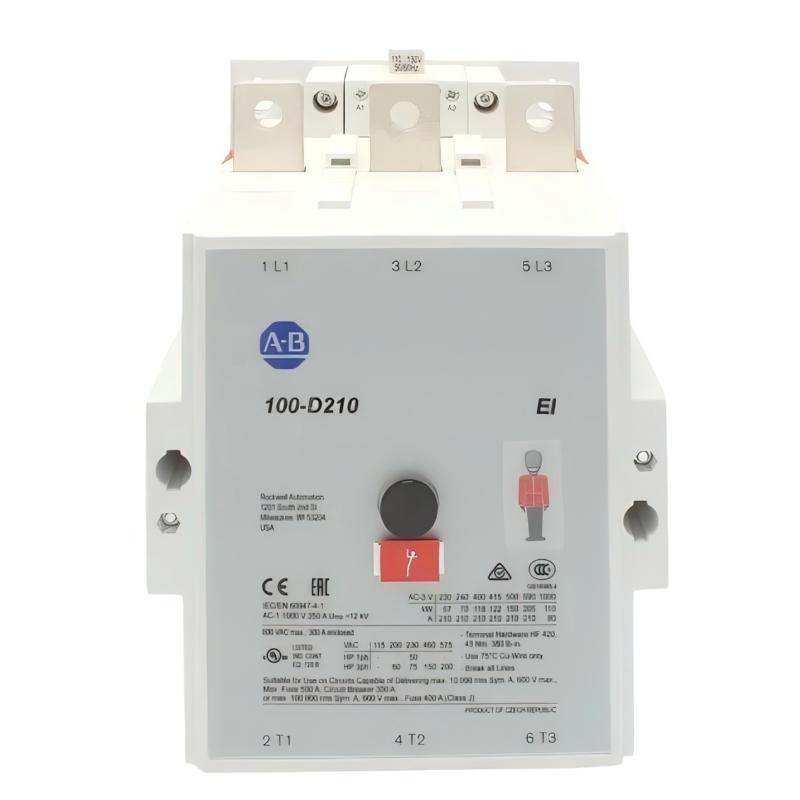
The Allen-Bradley 100S-D210EA22BC is a heavy-duty IEC safety contactor (210A frame) used in motor control centers and safety-rated power isolation systems.
It typically handles:
- Large motor isolation (up to ~132 kW class applications)
- Safety shutdown circuits (E-Stop / safety PLC output)
- Redundant safety feedback via mechanically linked contacts
- High inrush industrial loads (compressors, pumps, crushers)
Its structure includes:
- 3 main power poles (L1/L2/L3)
- Mechanically linked auxiliary contacts for feedback logic
- Electronic coil design (wide voltage tolerance range)
Field insight: In one cement plant, repeated motor “no-start” events were traced not to PLC logic, but to undervoltage on the coil during simultaneous compressor starts, which prevented full pull-in of the contactor.
Installation Conditions (Critical Engineering Checks)
1. Coil Supply Stability (Most Critical Point)
- Coil voltage must remain within rated range during energization
- Avoid shared 24V or control supply with heavy inductive loads
- Check for voltage dip during plant-wide startup
In real field cases, coil voltage dropping below ~85% of nominal causes contact chatter and partial engagement, which is dangerous in safety circuits.
2. Power Circuit Requirements
- Ensure correct phase alignment (L1/L2/L3)
- Tighten all power terminals to torque specification
- Use proper busbar alignment for high-current applications
- Verify upstream short-circuit protection coordination
A loose busbar connection in one steel mill caused localized overheating exceeding 90°C at the terminal point.
3. Safety Feedback Wiring
- Always wire NC mirror contacts into safety PLC loop
- Ensure “contact open = safe state” logic is correctly implemented
- Do not bypass auxiliary feedback circuits
Field observation: Missing feedback wiring often causes safety PLC to assume contactor failure even when mechanically operating correctly, resulting in false trip conditions.
Installation Procedure (Field Engineering Practice)
Step 1: Mechanical Mounting
- Install on DIN rail or mounting plate
- Ensure rigid fixation (high-current devices generate vibration)
- Maintain clearance for heat dissipation
Step 2: Coil Wiring
- Connect A1/A2 to safety relay output
- Add suppression device (diode or RC snubber)
- Avoid long unshielded coil runs
Without suppression, one packaging line experienced PLC input noise spikes during every coil release event.
Step 3: Power Wiring
- Connect main terminals L1/L2/L3 securely
- Verify phase rotation if driving motors
- Ensure cable sizing matches 210A load class
Step 4: Safety Feedback Loop
- Wire mirror contacts into safety PLC input
- Verify status changes during ON/OFF cycles
- Confirm feedback timing consistency (<100 ms typical)
Commissioning Strategy (Engineering Logic)
Cold Start Validation
- Check coil pull-in behavior (no hesitation or humming)
- Verify full contact closure
- Monitor voltage stability during activation
Safety Loop Test
- Trigger E-Stop condition
- Confirm immediate drop-out of contactor
- Verify PLC receives correct feedback state
Load Stress Test
- Start motor under full load
- Observe voltage dip during inrush current
- Monitor temperature rise at terminals
In one pumping station, coil dropout only occurred during simultaneous motor starts due to shared transformer undersizing.