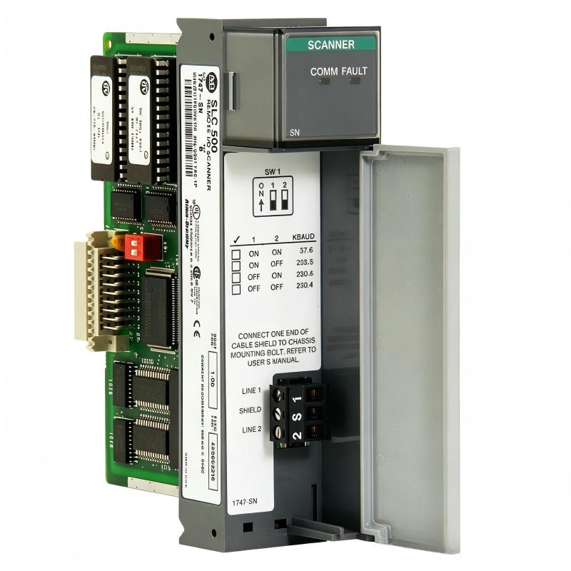
Allen-Bradley 1747-SN/B SLC500 Remote I/O Scanner Module Installation Guide (Setup & Commissioning)
Allen-Bradley 1747-SN/B SLC500 Remote I/O Scanner Module installation problems are usually caused by incorrect remote rack configuration, communication wiring issues, or mismatched I/O addressing rather than a failed scanner module. In many SLC500 legacy automation systems, the scanner can power up normally while remote I/O devices remain inactive because the Remote I/O link parameters do not match the actual field configuration.
The Allen-Bradley 1747-SN/B SLC500 Remote I/O Scanner Module provides communication between an SLC500 processor and distributed Remote I/O devices. It allows control systems to move I/O points away from the main PLC cabinet, reducing field wiring distance and improving machine architecture flexibility.
Allen-Bradley 1747-SN/B Remote I/O Scanner Module Application Overview
The 1747-SN/B operates as the master scanner for a Remote I/O network. It collects input data from remote racks and transfers output commands from the SLC500 processor to field devices.
Typical system structure:
SLC500 Processor
        |
1747-SN/B Scanner Module
        |
Remote I/O Network
        |
Remote Adapter
        |
Digital / Analog I/O Modules
Common applications include:
- Automotive production equipment
- Packaging machinery
- Conveyor systems
- Process control panels
- Large assembly machines
In one factory expansion project, an SLC500 control system was extended with three remote I/O panels using a 1747-SN/B scanner.
During commissioning:
- PLC processor status: RUN
- Scanner module status: Normal
- Remote inputs: No response
- Remote outputs: Not activating
The first assumption was that the remote I/O adapter had failed.
The engineering team checked the complete communication chain and found that the remote rack addressing did not match the scanner configuration.
After correcting the addressing:
- Remote inputs updated correctly
- Output commands became stable
- No hardware replacement was required
Allen-Bradley 1747-SN/B Installation Preparation and Hardware Inspection
Before installing the Remote I/O scanner module, engineers should confirm the complete system design.
Important preparation checks:
- SLC500 chassis compatibility
- Available installation slot
- Processor communication capability
- Remote rack planning
- Communication cable condition
- Field power supply stability
Recommended installation checklist:
| Check Item | Engineering Requirement |
|---|---|
| Chassis power | Remove power before installation |
| Scanner position | Correct SLC rack slot |
| Remote address | Unique rack assignment |
| Cable routing | Away from high-noise equipment |
| Configuration | Match PLC project settings |
A common field mistake is installing the scanner module correctly but leaving outdated remote rack settings from previous equipment.
Allen-Bradley 1747-SN/B Remote I/O Wiring Installation and Network Setup
Remote I/O communication reliability depends heavily on physical wiring quality.
During installation, verify:
- Communication cable continuity
- Connector condition
- Shield grounding
- Cable routing
- Network termination
In one water treatment control system, operators reported random loss of remote valves.
Field observations:
Before correction:
- Remote communication dropped several times per day
- Output response became delayed
- PLC remained in normal operation
Electrical inspection showed:
- Loose communication terminal
- Poor shield connection
- Intermittent signal interruption caused by cabinet vibration
After repairing the connection:
- Communication remained stable
- Remote valves responded normally
- No further communication alarms occurred
The issue was caused by network wiring, not the 1747-SN/B module.
Allen-Bradley 1747-SN/B SLC500 PLC Configuration and Remote Rack Setup
Correct configuration is critical for successful commissioning.
The engineer must verify:
- Scanner module slot assignment
- Remote rack addressing
- I/O image mapping
- Data table configuration
- Communication status monitoring
Typical control logic:
IF Scanner_Status = OK
AND Remote_IO_Ready = TRUE

THEN
Allow Machine Operation
This prevents machine operation when field communication is unavailable.
During commissioning, monitor:
- Scanner diagnostic status
- Remote input changes
- Output command execution
- Communication update timing
A frequent commissioning problem is that PLC logic is correct, but the remote I/O data address does not match the physical rack arrangement.
Allen-Bradley 1747-SN/B Remote I/O Scanner Commissioning Validation
A proper commissioning process should verify the complete control loop.
Communication Testing
Check:
- Scanner communication status
- Remote rack availability
- Data exchange stability
Functional Testing
Verify:
- Input signal response
- Output device activation
- Machine sequence operation
Example commissioning data:
Initial condition:
- Remote output delay: 1.5 seconds
- Communication retries: 30/hour
After correction:
- Output response: below 100 ms
- Communication retries: 0
A successful 1747-SN/B installation requires cooperation between PLC configuration, scanner settings, remote adapters, and field wiring.