Allen-Bradley 20AD5P0A0AYYNNG0 PowerFlex 70 AC Drive Installation Guide (Wiring & Commissioning)
Allen-Bradley 20AD5P0A0AYYNNG0 PowerFlex 70 AC Drive installation issues are usually caused by incorrect motor wiring, improper parameter configuration, insufficient grounding, or incorrect control signal setup rather than drive hardware failure. In industrial motor control applications, a PowerFlex 70 AC Drive can power up normally while still failing to control motor speed correctly because commissioning parameters, feedback settings, or application configuration are incomplete.
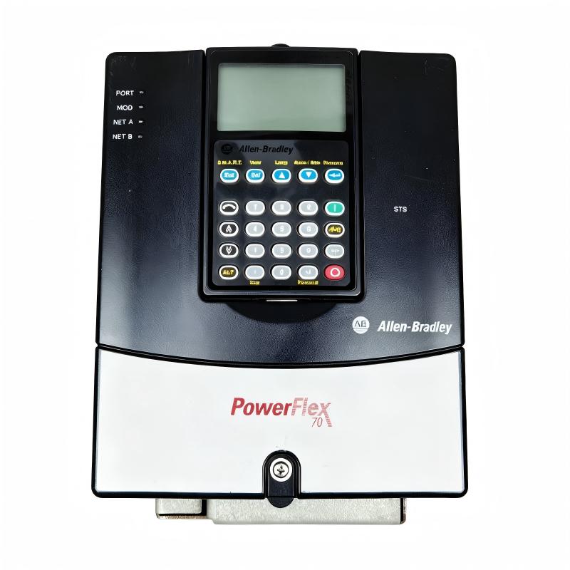
The Allen-Bradley 20AD5P0A0AYYNNG0 PowerFlex 70 AC Drive is an adjustable frequency drive designed for industrial motor speed control applications. It provides variable frequency control for three-phase AC motors and is commonly used in conveyors, pumps, fans, machine tools, and production equipment where precise motor control is required.
Allen-Bradley 20AD5P0A0AYYNNG0 PowerFlex 70 AC Drive Application Overview
The PowerFlex 70 AC Drive controls motor operation by converting fixed-frequency AC input power into adjustable output frequency and voltage.
Typical system architecture:
Three Phase AC Power
          |
          |
20AD5P0A0AYYNNG0 PowerFlex 70 Drive
          |
          |
Three Phase Motor
          |
          |
Mechanical Load
Main functions include:
- Variable motor speed control
- Acceleration and deceleration management
- Motor protection
- Process control optimization
- Industrial automation integration
Typical applications:
- Conveyor systems
- Pump stations
- HVAC equipment
- Packaging machinery
- Material handling systems
In one packaging production line, engineers installed a PowerFlex 70 AC Drive to replace a traditional motor starter.
During initial commissioning:
- Drive power-up: Normal
- Display operation: Normal
- Motor rotation: Incorrect
The engineering team initially suspected incorrect motor phase wiring.
The troubleshooting process included:
- Checking input and output wiring
- Reviewing motor nameplate data
- Verifying drive parameters
- Testing acceleration and speed commands
Measured condition:
Before correction:
- Input voltage: 480 VAC
- Drive status: Ready
- Motor current: Higher than expected
- Rotation direction: Reverse
After correction:
- Motor rotation corrected
- Current reduced to normal range
- Speed control became stable
The issue was caused by commissioning configuration, not drive failure.
Allen-Bradley 20AD5P0A0AYYNNG0 Installation Preparation and Electrical Planning
Before installing the PowerFlex 70 AC Drive, engineers should evaluate the complete motor control system.
Preparation requirements:
- Confirm motor voltage and current rating
- Verify incoming power supply
- Check grounding system
- Prepare control wiring
- Review application requirements
Installation checklist:
| Inspection Item | Engineering Requirement |
|---|---|
| Input power | Match drive rating |
| Motor cable | Correct size and length |
| Ground connection | Proper grounding |
| Control signals | Correct wiring |
| Environment | Suitable installation location |
A common field mistake is replacing a motor starter with a variable frequency drive without reviewing motor parameters.
Before commissioning, engineers should confirm:
- Motor rated voltage
- Full load current
- Maximum operating frequency
- Acceleration requirements
- Deceleration requirements
Allen-Bradley 20AD5P0A0AYYNNG0 PowerFlex 70 Wiring Installation Process
Correct wiring is essential for reliable AC drive operation.
Main wiring areas:
Power Input Wiring
Verify:
- Three-phase input connection
- Correct voltage level
- Proper protective devices
Motor Output Wiring
Check:
- U/V/W motor connections
- Motor grounding
- Cable insulation condition
Control Wiring
Verify:
- Start/stop signals
- Speed reference input
- Digital and analog signals
In one field installation case:
Initial condition:
- Drive powered correctly
- Motor failed to accelerate smoothly
Inspection found:
- Analog speed reference wiring had electrical noise
- Shield grounding was incorrect
After correction:
- Speed command became stable
- Motor acceleration improved
- Process operation returned to normal
Allen-Bradley 20AD5P0A0AYYNNG0 Setup and Parameter Configuration
The commissioning stage requires correct drive parameter setup.
Important configuration areas:
- Motor data entry
- Speed reference source
- Acceleration time
- Deceleration time
- Control mode selection
Typical commissioning logic:
IF Motor_Data = Correct
AND Control_Source = Configured
AND Command_Signal = Valid

THEN

Enable Motor Operation
Engineers should verify:
- Motor starts smoothly
- Current remains within limits
- Speed follows reference command
- Fault monitoring operates correctly
Field experience shows that incorrect parameter settings often appear as hardware problems.
Allen-Bradley 20AD5P0A0AYYNNG0 Commissioning Validation and Performance Testing
Final commissioning should verify the complete drive system.
Motor Operation Test
Check:
- Forward/reverse rotation
- Acceleration performance
- Speed stability
Protection Test
Verify:
- Overcurrent protection
- Overvoltage response
- Motor overload protection
Example commissioning results:
Before optimization:
- Motor acceleration time: Unstable
- Current fluctuation: High
- Speed deviation: Large
After optimization:
- Smooth acceleration
- Stable motor current
- Accurate speed control
A successful Allen-Bradley 20AD5P0A0AYYNNG0 installation requires correct wiring, accurate parameter setup, and complete commissioning validation.