Technical Tutorial

  1. Home
  2. Products
  3. Technical Tutorial
  4. Allen-Bradley 1336-BDB-SP31C Gate Driver Installation Guide (Replacement & Commissioning)
Allen-Bradley 1336-BDB-SP31C Gate Driver Installation Guide (Replacement & Commissioning)

Allen-Bradley 1336-BDB-SP31C Gate Driver Installation Guide (Replacement & Commissioning)


Allen-Bradley 1336-BDB-SP31C gate driver installation problems are usually caused by incorrect board replacement procedures, poor connector contact, incompatible drive configuration, or damaged power switching components rather than the gate driver board itself. In industrial drive repair projects, a newly installed gate driver may appear normal while the inverter still produces faults because the firing signals, feedback circuits, and power stage components are not correctly matched.

The Allen-Bradley 1336-BDB-SP31C Gate Driver is a replacement gate drive board used in Allen-Bradley 1336 series AC drives. It provides the interface between the main control electronics and the power switching section, managing gate pulse transmission, isolation, and protection feedback for inverter power devices.
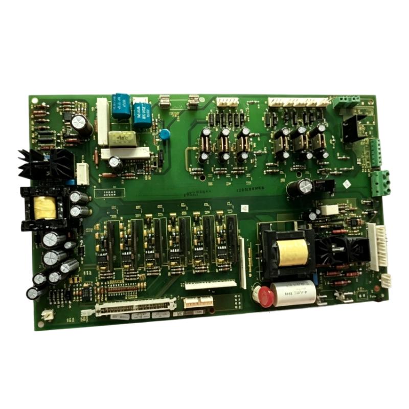


Allen-Bradley 1336-BDB-SP31C Gate Driver Application Overview

The gate driver is a critical control component inside an AC drive power system.

Typical drive structure:

Drive Control Board
          |
          |
Allen-Bradley 1336-BDB-SP31C Gate Driver
          |
          |
IGBT Power Module
          |
          |
Motor Output Stage

Main functions:

  • IGBT gate pulse control
  • Switching signal isolation
  • Fault feedback transmission
  • Power module protection
  • Drive output control

Typical applications:

  • Industrial motor drives
  • Conveyor systems
  • Machine automation equipment
  • Process control systems
  • Pump and fan applications

The gate driver directly affects inverter switching performance. Any abnormal condition in this section may result in:

  • Overcurrent faults
  • DC bus trips
  • Motor output loss
  • Drive startup failure

In one industrial maintenance project, engineers replaced a damaged gate driver board in an Allen-Bradley 1336 drive.

After replacement:

  • Drive keypad: Normal
  • Control power: Available
  • Motor output: Missing

The initial assumption was that the replacement board was defective.

The engineering team performed a field investigation:

  • Checked gate pulse signals
  • Verified connector installation
  • Tested power transistor feedback
  • Reviewed fault history

Measured condition:

Before correction:

  • Control voltage: Normal
  • Gate command: Present
  • Output stage response: Abnormal
  • Fault feedback: Active

Further inspection found that one connection between the gate driver and power module was not properly seated.

After correcting the connection:

  • Gate signals became stable
  • Drive output recovered
  • Motor operated normally

The failure was caused by installation connection issues rather than the gate driver board.


Allen-Bradley 1336-BDB-SP31C Installation Preparation and Drive Inspection

Before installing the 1336-BDB-SP31C gate driver, engineers should inspect the complete drive system.

Preparation requirements:

  • Confirm replacement board model
  • Record original drive parameters
  • Disconnect DC bus power completely
  • Inspect surrounding power components
  • Check connector condition

Installation checklist:

Inspection ItemEngineering Requirement
Board replacementMatch original drive specification
DC busFully discharged before service
ConnectorsSecure and correctly positioned
Power moduleCheck for short circuit damage
Cooling systemVerify normal operation

A common repair mistake is replacing the gate driver without checking the IGBT module.

If the power switching device has failed, a new gate driver may immediately experience:

  • Short circuit protection
  • Gate fault alarms
  • Repeated failure

A complete power stage inspection should always be performed.


Allen-Bradley 1336-BDB-SP31C Gate Driver Wiring and Hardware Installation

Correct connection is essential for reliable switching control.

Control Signal Connection

Verify:

  • Gate signal interface
  • Feedback communication
  • Control board connection
  • Connector orientation

Incorrect connection may cause:

  • Missing gate pulses
  • Fault feedback errors
  • Drive output shutdown

Power Stage Interface Inspection

Check:

  • IGBT gate connections
  • Power module interface
  • Protection circuits

During one field repair:

Initial condition:

  • Replacement gate driver installed
  • Drive powered successfully
  • Immediate fault after run command

Engineering measurements:

  • Control board communication: Normal
  • Gate driver supply voltage: Normal
  • Power feedback: Incorrect

The inspection found:

  • A connector pin was slightly damaged during previous maintenance

After replacing the damaged connector:

  • Feedback signals returned
  • Drive enabled normally
  • Motor operation recovered

Allen-Bradley 1336-BDB-SP31C Setup and Commissioning Procedure

After installing the gate driver, engineers should verify the interaction between the control board and power stage.

Important commissioning checks:

  • Gate pulse response
  • Fault feedback status
  • Motor output voltage
  • Current response

Typical diagnostic logic:

IF Control_Command = Active
AND Gate_Signal = Correct
AND Feedback = Normal

THEN

Enable Inverter_Output

During commissioning, engineers should monitor:

  • DC bus condition
  • Output current
  • Fault codes
  • Switching behavior

A gate driver replacement should not be considered complete until the drive completes a full operational test.


Allen-Bradley 1336-BDB-SP31C Performance Validation and Final Testing

Final testing should include:

Electrical Verification

Check:

  • Control voltage
  • Gate feedback
  • Output switching

Motor Operation Test

Verify:

  • Startup behavior
  • Acceleration response
  • Running current
  • Fault protection

Example commissioning results:

Before correction:

  • Drive entered protection mode
  • Motor output unavailable
  • Fault occurred immediately

After correction:

  • Switching control restored
  • Motor started smoothly
  • Drive returned to normal operation

A successful Allen-Bradley 1336-BDB-SP31C installation requires correct replacement procedures, careful wiring inspection, and complete power stage testing.


Tags:

Look forward to your comments!Comment
Latest comments

0.0
Points

Need Assistance? Chat with Us on WhatsApp!
Need Assistance? Click to Inquire
Back to top