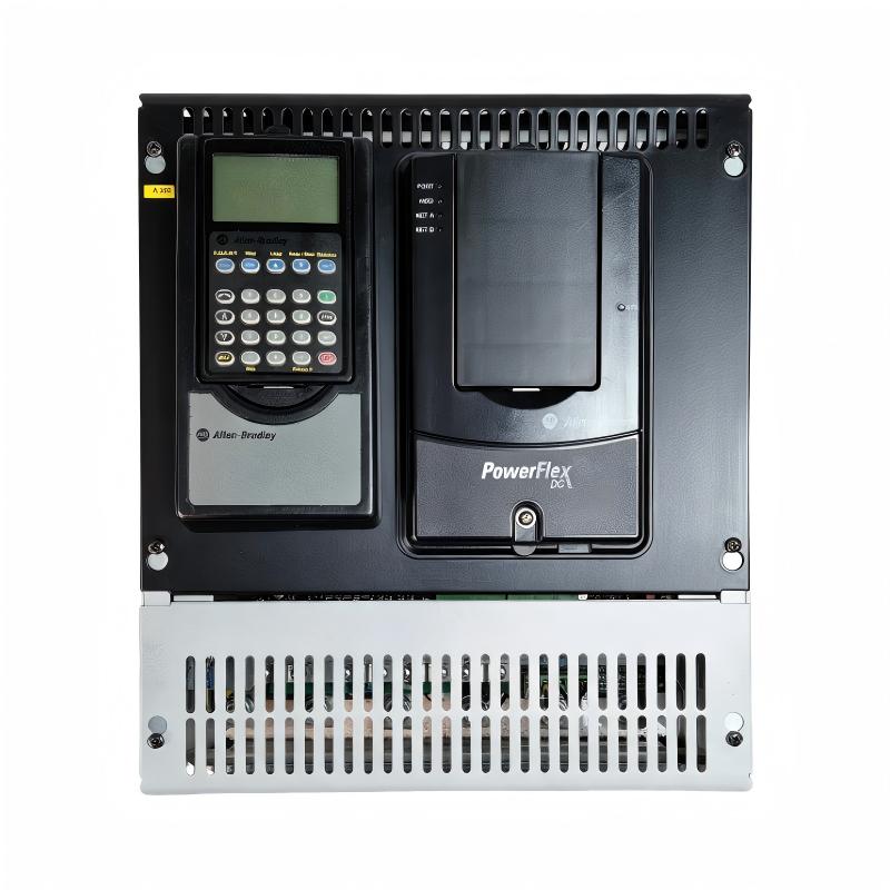
Allen-Bradley 20P21AD207RA0NNN PowerFlex DC Drive Troubleshooting Guide (Fault Diagnosis)
Allen-Bradley 20P21AD207RA0NNN PowerFlex DC Drive faults are commonly caused by incorrect feedback signals, field circuit problems, motor parameter mismatch, overload conditions, or application changes rather than immediate drive hardware failure. Proper troubleshooting requires analyzing the complete DC motor control loop.
This article describes a field case where a PowerFlex DC Drive generated repeated speed regulation faults during production operation.
Allen-Bradley 20P21AD207RA0NNN PowerFlex DC Drive Fault Symptoms
Typical fault symptoms include:
- Motor speed unstable
- Drive trips during operation
- Current increases unexpectedly
- Speed feedback alarms appear
- Motor cannot maintain commanded speed
Field case:
A production machine using a DC motor experienced speed fluctuation after several years of stable operation.
Initial observations:
- PLC command: Normal
- Drive communication: Normal
- Motor speed: Changing continuously
The maintenance team suspected:
- DC motor aging
- Drive control board failure
- Feedback sensor damage
Engineers began troubleshooting from the control loop.
Allen-Bradley 20P21AD207RA0NNN Fault Diagnosis Process and Signal Analysis
Troubleshooting path:
PLC Speed Command||PowerFlex DC Drive||Motor Feedback System||DC Motor
Engineers checked:
- Drive fault history
- Armature current
- Field current
- Feedback signal
Diagnostic results:
- Command signal: Normal
- Armature circuit: Normal
- Speed feedback: Unstable
The fault was isolated to the feedback section.
Allen-Bradley 20P21AD207RA0NNN Speed Feedback Fault Investigation
Field measurements:
Before repair:
- Speed command: Stable
- Feedback signal: Intermittent
- Motor speed variation: Significant
Engineers inspected:
- Encoder wiring
- Feedback terminals
- Shield connection
- Mechanical mounting
The investigation found:
- Encoder signal cable had insulation damage caused by vibration
Technical impact:
The damaged cable caused:
- Incorrect speed feedback
- Continuous speed correction
- Unstable motor operation
The PowerFlex DC Drive responded correctly based on incorrect feedback information.
Allen-Bradley 20P21AD207RA0NNN Root Cause Analysis and Recovery
The final root cause was feedback signal interruption.
Original condition:
- Encoder signal stable
- Speed regulation normal
Failure condition:
- Cable damage occurred
- Feedback signal became unstable
- Speed loop continuously adjusted output
Engineering conclusion:
The problem was caused by feedback wiring deterioration, not the DC drive itself.
Allen-Bradley 20P21AD207RA0NNN Troubleshooting Repair and System Recovery
Corrective actions:
Feedback System Repair
Performed:
- Replaced damaged feedback cable
- Checked shielding
- Verified encoder signals
Drive Performance Verification
Tested:
- Speed response
- Current regulation
- Continuous operation
Final results:
Before repair:
- Speed fluctuation affected production quality
- Operators adjusted settings frequently
After repair:
- Stable feedback signal
- Accurate speed control
- Normal production restored
Allen-Bradley 20P21AD207RA0NNN Common Fault Patterns and Diagnostic Methods
Field Loss Fault
Symptoms:
- Motor speed increases unexpectedly
- Drive trips during operation
Diagnosis:
- Check field current
- Verify field wiring
- Inspect excitation circuit
Speed Feedback Fault
Symptoms:
- Speed unstable
- Incorrect motor response
Diagnosis:
- Measure feedback signal
- Inspect encoder wiring
- Verify scaling parameters
Overcurrent Fault
Symptoms:
- Drive trips during acceleration
Diagnosis:
- Check motor load
- Verify current settings
- Inspect mechanical resistance
Allen-Bradley 20P21AD207RA0NNN Long-Term Maintenance Strategy
For reliable PowerFlex DC Drive operation:
- Keep motor parameter records
- Inspect feedback wiring regularly
- Monitor current trends
- Check field circuit condition
- Record fault history
A practical engineering rule:
“When troubleshooting an Allen-Bradley 20P21AD207RA0NNN PowerFlex DC Drive fault, analyze the motor control loop before replacing drive hardware.”
Recommended troubleshooting sequence:
Fault history review → Power inspection → Field circuit check → Feedback measurement → Parameter verification → Final motor test.