ABB Vital 3 2TLA020070R4400 Safety Controller Installation Guide (Wiring & Commissioning)
ABB Vital 3 2TLA020070R4400 safety controller installation issues are usually caused by incorrect safety loop wiring, improper sensor connection, configuration mistakes, or incomplete safety validation rather than a defective safety controller. In industrial safety systems, the safety controller must continuously evaluate input devices, output circuits, and monitored components, so even a small wiring deviation can prevent machine enable or trigger unexpected safety stops.
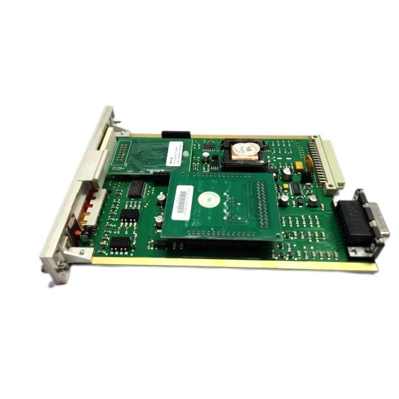
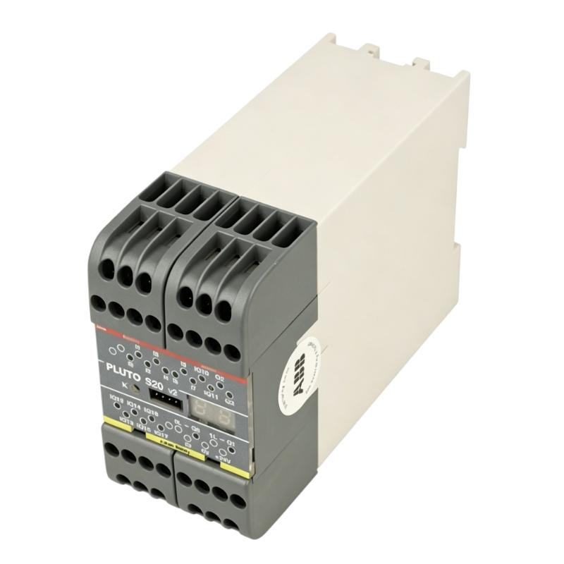
The ABB Vital 3 2TLA020070R4400 Safety Controller is designed for safety monitoring applications where reliable evaluation of safety devices is required. It is commonly integrated with safety sensors, emergency stops, safety switches, and machine protection systems to create a dependable safety control architecture.
ABB Vital 3 2TLA020070R4400 Safety Controller Application Overview
The Vital 3 safety controller provides a centralized method for monitoring safety devices and controlling safety-related outputs.
Typical safety system architecture:
Emergency Stop
Safety Sensor
Safety Switch
      |
      |
      v
ABB Vital 3 2TLA020070R4400 Safety Controller
      |
      |
Safety Outputs
      |
      |
Contactors / Drives / Machine Enable Circuit
Typical applications:
- Industrial machine safety systems
- Packaging equipment
- Automated production lines
- Robot cells
- Material handling systems
- Safety gate monitoring
Main functions:
- Safety device monitoring
- Dual-channel safety evaluation
- Safety output control
- Fault detection
- Machine stop protection
Unlike standard PLC modules, a safety controller must evaluate whether the complete safety chain is trustworthy.
The safety chain normally includes:
- Input device condition
- Wiring integrity
- Controller diagnostics
- Output feedback
- External switching devices
ABB Vital 3 2TLA020070R4400 Installation Preparation and Safety System Planning
Before installing the Vital 3 safety controller, engineers should analyze the complete safety circuit.
Preparation requirements:
- Review safety circuit drawings
- Confirm safety device compatibility
- Identify input channels
- Verify output requirements
- Check external contactor feedback
Installation checklist:
| Inspection Item | Engineering Requirement |
|---|---|
| Safety device wiring | Correct channel connection |
| Emergency stop circuit | Dual-channel verification |
| Output circuit | Correct safety relay interface |
| Feedback loop | Proper monitoring connection |
| Power supply | Stable control voltage |
A common field mistake is treating a safety controller installation like a standard relay installation.
Safety systems require additional checks:
- Channel consistency
- Fault detection capability
- Reset logic
- Feedback monitoring
Incorrect safety wiring may cause:
- Safety output unavailable
- Continuous safety fault
- Machine unable to restart
ABB Vital 3 2TLA020070R4400 Safety Controller Wiring Installation
Correct wiring is essential for reliable safety operation.
Safety Input Wiring Verification
Engineers should check:
- Emergency stop terminals
- Safety sensor connections
- Dual-channel wiring
- Cable identification
Incorrect input wiring can create:
- Channel mismatch faults
- Safety lockout
- Unexpected machine stop
Safety Output and Feedback Wiring Check
Verify:
- Output contacts
- Contactor feedback
- Reset circuit
- External device monitoring
During one machine commissioning project, engineers installed an ABB Vital 3 safety controller on a robotic workstation.
Initial condition:
- Controller powered normally
- Safety input indicators active
- Machine enable unavailable
The first assumption was a controller configuration problem.
The engineering team checked:
- Emergency stop loop
- Safety output wiring
- Contactor feedback circuit
Measured condition:
Before correction:
- Safety inputs: Normal
- Controller status: Healthy
- Output enable: Blocked
Further inspection found:
- External contactor feedback contact remained open because the auxiliary contact wiring was incorrect.
After correcting the feedback loop:
- Safety output activated
- Robot cell enabled normally
- Commissioning completed successfully
The fault was caused by external safety circuit wiring rather than the ABB Vital 3 controller.
ABB Vital 3 2TLA020070R4400 Setup and Safety Configuration
The setup process focuses on ensuring that the safety controller correctly evaluates the connected devices.
Important checks:
- Input device arrangement
- Reset behavior
- Output monitoring
- Safety circuit logic
Typical safety diagnostic logic:
IF Safety_Input = Valid
AND Feedback = Correct
AND Reset_Command = Accepted

THEN

Enable_Safety_Output
Engineers should verify:
- Normal operating condition
- Emergency stop response
- Safety gate opening response
- Fault recovery behavior
A safety system should never be considered commissioned only because the machine starts.
The correct validation method is testing every safety-related action.
ABB Vital 3 2TLA020070R4400 Commissioning Validation and Performance Testing
Final commissioning requires functional safety testing.
Safety Input Test
Verify:
- Emergency stop activation
- Safety sensor response
- Safety switch operation
Safety Output Test
Check:
- Machine shutdown
- Drive disable function
- Contactor release
Restart Test
Confirm:
- Correct reset sequence
- No automatic unsafe restart
A field commissioning example:
Before correction:
- Safety circuit remained locked
- Operator could not restart equipment
After correction:
- Emergency stop function verified
- Reset sequence operated correctly
- Machine safety validation completed
A successful ABB Vital 3 2TLA020070R4400 installation requires correct wiring, safety circuit verification, and complete functional testing.