Siemens 6AG1332-5HF00-2AB0 Analog Output Module Installation Guide: Wiring and Commissioning
Siemens 6AG1332-5HF00-2AB0 analog output module installation depends on correct signal wiring, channel configuration, power-supply verification, and careful commissioning of the connected field devices. When an analog output does not produce the expected process value, engineers should verify the configured output range and wiring before assuming that the module has failed.
Siemens 6AG1332-5HF00-2AB0 Analog Output Module Overview
The Siemens 6AG1332-5HF00-2AB0 is an analog output module intended for industrial automation applications where a PLC system needs to generate controlled analog signals for field devices.
Unlike a digital output module that normally switches between discrete states, an analog output module continuously represents a process command through an electrical signal. This makes correct System Configuration particularly important.
Typical applications include:
- Control valves
- Variable-speed drive references
- Actuator commands
- Temperature-control systems
- Pressure-control loops
- Flow-control equipment
- Process instrumentation
In practical installations, the quality of the analog signal depends on the module configuration as well as the external wiring and receiving device.
Siemens 6AG1332-5HF00-2AB0 Installation Preparation
Before mounting the module, confirm that the PLC rack, backplane, power supply, and surrounding modules are suitable for the intended configuration.
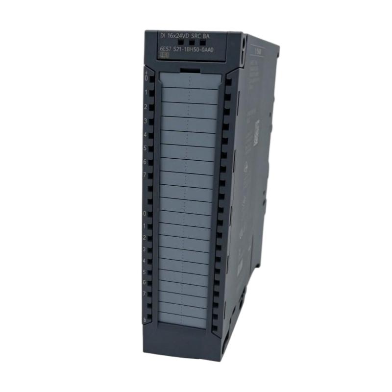
The available product dimensions are:
| Parameter | Specification |
|---|---|
| Manufacturer | Siemens |
| Model | 6AG1332-5HF00-2AB0 |
| Product Type | Analog Output Module |
| Dimensions | 40 × 125 × 120 mm |
| Weight | 0.328 kg / 0.72 lb |
Inspect the module housing and terminals before installation. Check for damaged connectors, contamination, cracked plastic, or signs of previous overheating.
The cabinet should also provide appropriate environmental conditions. Excessive heat, condensation, vibration, and contamination can affect long-term analog signal stability.
Siemens 6AG1332-5HF00-2AB0 Wiring Strategy
Analog signals are more sensitive to wiring quality than ordinary digital signals. A technically correct module can still produce unstable process values if the field wiring is poorly arranged.
During installation, verify:
- Channel assignment
- Signal-wire polarity
- Common/reference connections
- Cable shielding
- Terminal tightness
- Separation from high-voltage conductors
- Separation from motor and inverter cables
- Correct connection at the receiving device
For long cable runs, avoid routing analog signal cables alongside high-current switching conductors whenever possible.
In a cabinet containing VFDs, contactors, or servo drives, electromagnetic interference can appear as unstable analog readings even though the PLC hardware itself is operating normally.
Siemens 6AG1332-5HF00-2AB0 Analog Output Setup
The Setup phase should begin with the intended process signal.
For example, if an analog output is being used as a reference for a drive, the engineer needs to establish:
PLC value → configured engineering range → electrical output → receiving-device interpretation
A mismatch at any point can produce an apparently incorrect output.
Before commissioning, verify that the PLC program, hardware configuration, and receiving equipment use compatible signal ranges.
Do not assume that a field device automatically interprets every analog signal in the same way. The receiving device must be configured for the same electrical signal standard used by the output channel.
Siemens 6AG1332-5HF00-2AB0 System Configuration Checks
The System Configuration should be checked before the analog output is connected to a production process.
Confirm:
- The correct Siemens module is installed.
- The module is correctly recognized by the PLC configuration.
- Channel parameters match the application.
- The PLC program addresses the intended channel.
- The field device is wired to the correct output.
- Signal reference connections are correct.
- The receiving equipment is configured for the intended signal.
- No diagnostic condition is active.
A useful commissioning method is to test the output at several known command values instead of checking only one point.
For example, command a low value, a middle value, and a high value and observe whether the field device responds proportionally.
Siemens 6AG1332-5HF00-2AB0 Commissioning and Signal Validation
During Commissioning, compare the PLC command with the actual measured output.
A practical diagnostic table can look like this:
| PLC Command | Expected Signal | Measured Signal | Result |
|---|---|---|---|
| Low command | Corresponding low output | Verify | Pass/Fail |
| Mid-range command | Corresponding mid output | Verify | Pass/Fail |
| High command | Corresponding high output | Verify | Pass/Fail |
If the PLC command changes correctly but the measured output does not, the investigation should move toward the module configuration, wiring, output channel, or receiving circuit.
If the electrical output changes correctly but the field device does not respond, the problem is more likely downstream of the Siemens analog output module.
This distinction saves considerable commissioning time.
Siemens 6AG1332-5HF00-2AB0 Field Commissioning Case
In one representative commissioning situation, an analog-controlled actuator remained near its minimum operating position even though the PLC program was generating a changing process command.
The first assumption was that the analog output module was defective.
The engineer instead compared three points:
PLC command → measured module output → actuator input
The PLC value changed normally. The measured analog signal also followed the command. The fault was therefore not in the PLC Controller or analog output channel.
Further inspection found that the receiving actuator had been configured for a different input range.
After the receiving-device configuration was corrected, the actuator followed the PLC command normally.
This is a typical example of why analog-output Fault Diagnosis should follow the entire signal path.
Siemens 6AG1332-5HF00-2AB0 Installation Troubleshooting
If the output is unstable during commissioning, inspect the installation systematically.
Possible causes include:
- Incorrect signal wiring
- Poor terminal contact
- Incorrect channel configuration
- Shielding problems
- Ground-reference problems
- Electrical interference
- Incorrect receiving-device configuration
- Faulty output channel
A fluctuating value should not immediately be interpreted as a defective Module.
If the instability appears only when a nearby motor or VFD starts, electromagnetic interference becomes a stronger diagnostic possibility.
Siemens 6AG1332-5HF00-2AB0 Installation Guide Long-Tail Keywords
Relevant long-tail searches include Siemens 6AG1332-5HF00-2AB0 Installation Guide, Siemens 6AG1332-5HF00-2AB0 analog output module installation, 6AG1332-5HF00-2AB0 wiring, Siemens analog output Setup, 6AG1332-5HF00-2AB0 Commissioning, Siemens analog output System Configuration, Siemens analog Module troubleshooting, and 6AG1332-5HF00-2AB0 signal testing.
The practical commissioning principle is to verify the complete signal chain rather than evaluating the PLC module in isolation.