Siemens 6AG1522-1BL01-7AB0 Digital Output Module Installation Guide (Wiring & Commissioning)
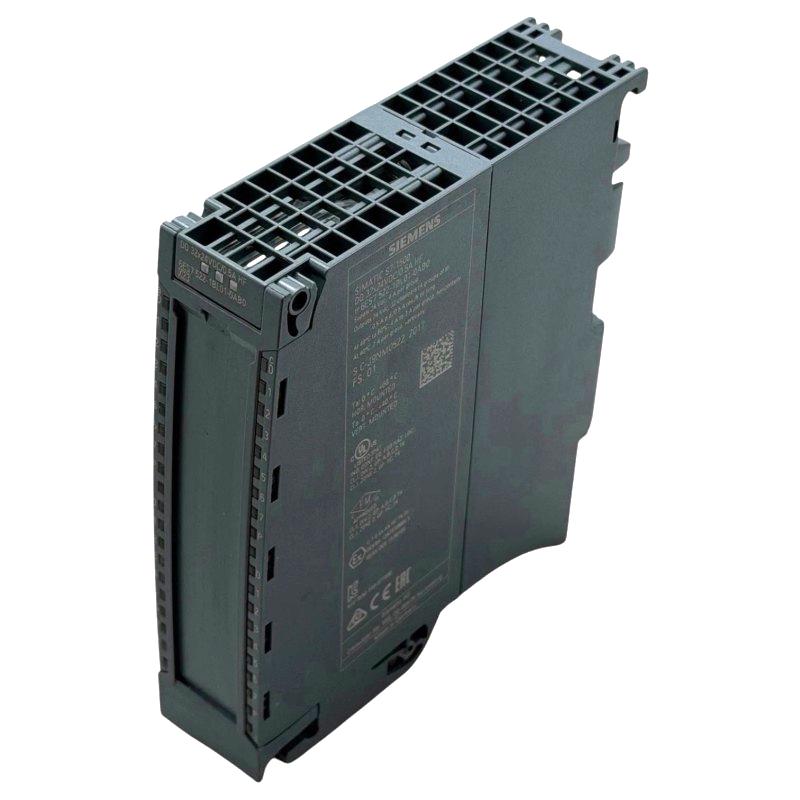
Siemens 6AG1522-1BL01-7AB0 Digital Output Module Installation Guide for S7-1500 PLC Systems
Siemens 6AG1522-1BL01-7AB0 Digital Output Module installation should begin with load identification, output-channel planning, and wiring verification rather than simply mounting the module and downloading the PLC program. For an S7-1500 system, an output module sits between PLC logic and real field loads, so a commissioning problem can originate from the module configuration, field wiring, load characteristics, or the connected actuator.
The Siemens 6AG1522-1BL01-7AB0 is a SIPLUS S7-1500 digital output module used to control discrete field devices from a PLC application. A reliable Installation Guide therefore needs to address the complete signal path: PLC configuration → output channel → terminal wiring → field load → actual machine response.
Siemens 6AG1522-1BL01-7AB0 Digital Output Module Application Planning
Before installing the Siemens 6AG1522-1BL01-7AB0, identify every output that will be connected to the module.
Typical applications include controlling:
- Solenoid valves
- Contactors
- Relays
- Indicator lamps
- Motor-control interfaces
- Pneumatic actuators
- Machine interlocks
Create an output list before wiring.
| Output | Field Device | Function | Test Requirement |
|---|---|---|---|
| Q0.x | Solenoid valve | Cylinder extend | Manual output test |
| Q0.x | Relay | Motor enable | Interlock verification |
| Q0.x | Indicator | Alarm status | Visual confirmation |
This simple document becomes useful during both Setup and Troubleshooting because it connects the PLC address with the actual device in the cabinet.
In one machine installation, two output wires were exchanged because the cabinet drawings had not been updated after a previous modification. The PLC program was correct, but the wrong pneumatic valve operated during the first test. Updating the wiring documentation before commissioning would have prevented the problem.
Siemens 6AG1522-1BL01-7AB0 Module Installation and Cabinet Preparation
The physical installation of the Siemens 6AG1522-1BL01-7AB0 Digital Output Module should be completed with attention to module alignment and neighboring S7-1500 components.
Before installation, check:
- Mounting rail condition
- Module position
- Backplane connection
- Terminal arrangement
- Cabinet clearance
- Wiring access
- Heat dissipation
The module should be installed without excessive mechanical force. After mounting, inspect the connection between the module and adjacent components.
Cable routing is also important. Digital output wiring carrying inductive loads should be separated appropriately from sensitive communication wiring.
A practical cabinet arrangement keeps high-current switching circuits away from Ethernet and other low-level communication cables wherever possible.
Siemens 6AG1522-1BL01-7AB0 Digital Output Wiring and Load Interface Setup
The most important part of Siemens 6AG1522-1BL01-7AB0 Setup is verifying that the electrical characteristics of the connected load match the output circuit.
Before connecting each load, identify:
- Operating voltage
- Nominal current
- Inrush current where applicable
- Load type
- Common supply arrangement
- Protection requirements
Particular attention should be given to inductive loads such as solenoids and relay coils.
When an output switches an inductive load, the circuit can generate a voltage transient when the load is de-energized. Appropriate suppression and protection should therefore be considered as part of the overall electrical design.
A field commissioning case involved an output channel controlling a solenoid valve. The PLC commanded the output correctly, but the channel repeatedly became unavailable after several switching cycles. Investigation found that the connected load generated significant electrical interference. After correcting the load suppression arrangement, the output operated consistently.
Siemens 6AG1522-1BL01-7AB0 PLC Hardware Configuration and System Setup
After wiring, the Siemens 6AG1522-1BL01-7AB0 must be represented correctly in the PLC engineering project.
The configuration should verify:
- Correct module identification
- Correct module position
- Channel addressing
- Output parameters
- Diagnostic settings where applicable
- Associated PLC logic
A useful engineering sequence is:
Physical Module
      ↓
Hardware Configuration
      ↓
Output Address Assignment
      ↓
Program Mapping
      ↓
Field Wiring Verification
      ↓
Online Test
Do not assume that the output address shown in the program corresponds automatically to the physical terminal you expect. Confirm the address against the actual hardware configuration and cabinet drawings.
Siemens 6AG1522-1BL01-7AB0 Output Channel Commissioning
The Siemens 6AG1522-1BL01-7AB0 Commissioning process should start with individual channels before automatic machine operation.
For each output, verify:
- PLC command is generated.
- Output status changes as expected.
- Voltage reaches the field circuit.
- Connected device responds.
- Machine sequence reacts correctly.
A practical test is to activate one output at a time while the machine is in a safe commissioning condition.
For example:
PLC Output Command ON
        ↓
Module Channel ON
        ↓
Measure Field Voltage
        ↓
Actuator Energized
        ↓
Feedback Signal Changes
This approach makes it easier to determine exactly where a signal path stops working.
Siemens 6AG1522-1BL01-7AB0 Digital Output Module Commissioning Case
During one machine commissioning project, an actuator connected to a digital output failed to operate.
The initial assumption was a defective output module.
The engineer measured the circuit instead of replacing the module immediately.
Results:
- PLC output command: ON
- Module status: ON
- Output-side voltage: Present
- Actuator terminal voltage: 0 V
The investigation then moved from the module toward the field device. A loose terminal was found between the output module and the actuator.
After tightening the connection, the actuator responded normally.
This is a useful example of practical PLC commissioning: the software command and module were both functioning, while the field wiring created the apparent output fault.
Siemens 6AG1522-1BL01-7AB0 Digital Output Module Validation
A completed Installation Guide should finish with functional validation rather than stopping after the module powers up.
The final test should include:
Channel Validation
Every configured output should be tested individually.
Load Validation
Each connected actuator should respond correctly.
Sequence Validation
The PLC program should operate the outputs in the intended order.
Interlock Validation
Safety and process conditions should prevent unintended output activation.
Continuous Operation
The module should be observed during representative machine cycles.
For production equipment, repeated switching tests are particularly useful for identifying loose terminals, incorrect load assumptions, or intermittent wiring problems.
Siemens 6AG1522-1BL01-7AB0 Digital Output Module Installation Best Practices
For long-term reliability, maintenance teams should retain:
- Updated I/O lists
- Electrical drawings
- PLC project backups
- Output load information
- Commissioning test records
During maintenance, technicians should also inspect terminal tightness and look for signs of overheating or abnormal switching behavior.
The Siemens 6AG1522-1BL01-7AB0 Digital Output Module should be commissioned as part of the complete PLC output circuit rather than as an isolated component. Careful wiring, System Configuration, and channel-by-channel validation provide a reliable foundation for industrial operation.