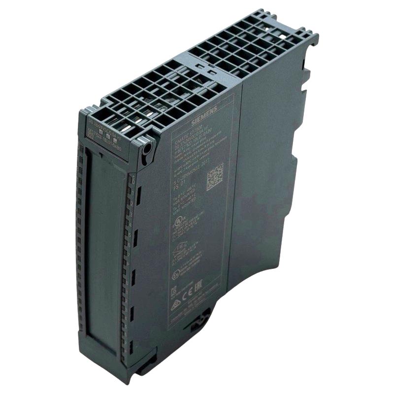
Siemens 6AG1522-1BL01-7AB0 Digital Output Module Troubleshooting Guide (Channel Fault Diagnosis & Repair)
Siemens 6AG1522-1BL01-7AB0 Digital Output Module Troubleshooting for Intermittent Output Channels
Siemens 6AG1522-1BL01-7AB0 Digital Output Module troubleshooting becomes much easier when an intermittent channel is analyzed as a complete electrical path instead of assuming that the module has failed. A channel that occasionally drops out may be affected by load behavior, wiring resistance, protection devices, or an unstable field connection.
For this Fault Diagnosis scenario, the key evidence is the difference between the PLC command, module status, measured output voltage, and actual actuator response.
Siemens 6AG1522-1BL01-7AB0 Digital Output Module Intermittent Fault Symptoms
A typical intermittent output fault may appear as:
- Actuator operates normally for several cycles
- Output occasionally turns off
- PLC logic continues to command the output
- Machine sequence stops
- Fault disappears after restarting equipment
The first distinction is between a logic fault and an electrical output fault.
If the PLC program removes the output command, the problem may be normal control logic.
If the PLC continues commanding the output but the field device loses power, the investigation should move toward the output circuit.
This distinction can save significant troubleshooting time.
Siemens 6AG1522-1BL01-7AB0 Output Command Versus Actual Channel Status
During Siemens 6AG1522-1BL01-7AB0 Fault Diagnosis, compare three points:
PLC command → module output → field device
For example:
PLC Logic = TRUE
       ↓
Module Channel = ON
       ↓
Field Voltage = ?
       ↓
Actuator = ?
If the first two conditions are correct but the field voltage disappears, inspect the wiring and load circuit.
If the PLC command changes unexpectedly, inspect the control logic, interlocks, timers, and sequence conditions.
This simple separation prevents a software issue from being incorrectly diagnosed as a hardware failure.
Siemens 6AG1522-1BL01-7AB0 Digital Output Voltage Fault Diagnosis
A practical measurement should be taken when the fault is actually occurring.
Suppose a solenoid output normally measures approximately 24 VDC.
During normal operation:
- PLC command: ON
- Module output: ON
- Field voltage: 24.1 VDC
- Solenoid: Energized
During the fault:
- PLC command: ON
- Module output: ON
- Field voltage: 8.4 VDC
- Solenoid: De-energized
The large difference immediately changes the troubleshooting direction.
The engineer should then measure voltage across:
- Output terminal
- Fuse or protection device
- Terminal block
- Field cable
- Load terminal
The location where voltage disappears identifies the likely fault area.
Siemens 6AG1522-1BL01-7AB0 Loose Terminal Fault Case Study
A field case involved a packaging machine where one pneumatic valve stopped approximately once every 50 machine cycles.
The maintenance team initially suspected an unstable digital output channel.
However, diagnostic observations showed:
- PLC output command remained continuously correct
- Output module status remained active
- Voltage at the module terminal: 24.0 VDC
- Voltage at the valve terminal during fault: 6.7 VDC
The engineer then performed a voltage-drop test along the cable path.
A loose terminal connection was found in an intermediate junction box.
After tightening and securing the connection:
- Normal voltage: approximately 24 VDC
- Fault frequency: 0 events during repeated testing
- Machine cycles completed: more than 200
The Siemens 6AG1522-1BL01-7AB0 module was not defective.
Siemens 6AG1522-1BL01-7AB0 Overload and Load-Related Troubleshooting
Another important Fault Diagnosis area is the connected load.
An output channel can behave abnormally when the connected device draws more current than expected or develops an electrical fault.
Possible causes include:
- Damaged solenoid coil
- Short circuit
- Incorrect load selection
- Excessive inrush current
- Wiring insulation failure
A useful diagnostic method is to disconnect the field load under controlled conditions and test the output circuit separately.
For example:
Intermittent Output
       ↓
Check PLC Command
       ↓
Check Channel Status
       ↓
Measure Output Voltage
       ↓
Disconnect Load Safely
       ↓
Test Channel Again
       ↓
Compare Results
If the output behaves normally without the load but fails when the load is connected, the field device becomes a major diagnostic target.
Siemens 6AG1522-1BL01-7AB0 Inductive Load Fault Diagnosis
Inductive loads deserve particular attention because switching them can create electrical transients.
Typical devices include:
- Relay coils
- Contactors
- Solenoid valves
- Electromagnetic actuators
A field engineer may observe a strange pattern: the output works during manual testing but becomes unreliable during automatic operation.
If the fault occurs immediately after an inductive load is switched off, examine the load circuit and suppression arrangement.
Useful observations include:
- Timing of the output fault
- Load current
- Voltage transient behavior
- Repetition frequency
- Relationship between output switching and communication disturbances
This timing-based analysis can distinguish an output-channel problem from a broader electrical interference issue.
Siemens 6AG1522-1BL01-7AB0 Module Versus Field Wiring Fault Diagnosis
Before replacing the Siemens 6AG1522-1BL01-7AB0, perform an isolation test where the application permits it.
The purpose is to determine whether the problem follows:
- The physical channel
- The field wiring
- The connected load
- The PLC program address
For example, if a fault moves with the field device and cable when connected to another correctly configured output, the original module channel may not be the cause.
If the fault remains associated with one specific hardware channel under controlled conditions, further module-level investigation is justified.
This kind of controlled comparison is more useful than replacing several components simultaneously.
Siemens 6AG1522-1BL01-7AB0 Output Module Repair Verification
After correcting the fault, the repair should be tested under the same conditions that originally produced the problem.
Verification should include:
- Repeated output switching
- Normal machine sequence
- Field voltage measurement
- Load response
- Diagnostic monitoring
If the original fault occurred every 50 cycles, testing only two cycles is not sufficient to demonstrate that the problem has disappeared.
A longer observation period provides stronger evidence that the repair addressed the actual root cause.
Siemens 6AG1522-1BL01-7AB0 Digital Output Module Troubleshooting Conclusion
The Siemens 6AG1522-1BL01-7AB0 Digital Output Module should be diagnosed as part of the complete output circuit. Intermittent behavior can originate from PLC logic, module status, field wiring, terminal connections, load characteristics, or electrical interference.
The most useful Troubleshooting approach is to compare the PLC command with the physical output and the actual load response, then use voltage and continuity measurements to locate where the signal path changes.
A disciplined Siemens 6AG1522-1BL01-7AB0 Fault Diagnosis process reduces unnecessary module replacement and provides a more reliable basis for repairing PLC output systems.