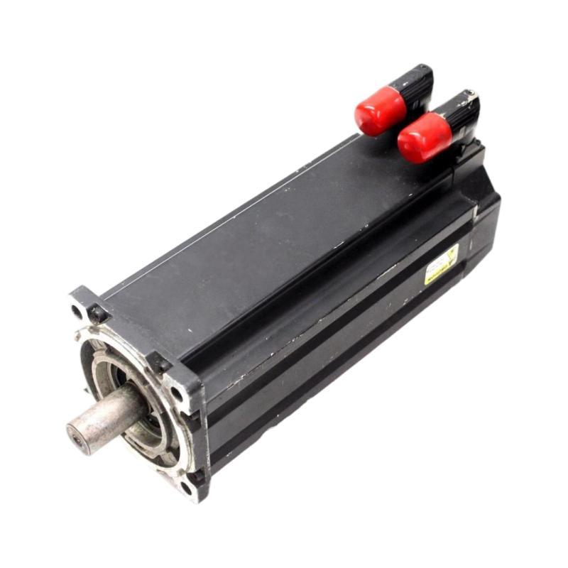
Allen Bradley MPL-B4560F-MK74AA Servo Motor Installation Guide for Motion Control System Setup and Commissioning
Allen Bradley MPL-B4560F-MK74AA Servo Motor Installation Overview
The Allen Bradley MPL-B4560F-MK74AA Servo Motor installation process should begin with drive compatibility verification, mechanical inspection, feedback wiring checks, and motor parameter configuration. Incorrect axis setup, cable routing, or mechanical alignment can cause commissioning delays even when the servo motor itself is functioning correctly.
In industrial motion control systems, the motor must work in coordination with the servo drive, motion controller, feedback device, and driven mechanism. A reliable Installation Guide therefore needs to cover the entire control loop rather than treating the motor as an isolated component.
Before proceeding, verify the complete catalog number and the applicable manufacturer documentation. Confirm the compatible drive, motor power and feedback cables, connector arrangement, and any brake requirements against the actual equipment configuration.
Preparing the Allen Bradley MPL-B4560F-MK74AA Servo Motor for Installation
Preparation reduces the risk of commissioning faults and unnecessary component replacement. Before mounting the Allen Bradley MPL-B4560F-MK74AA, inspect the motor housing, shaft, connectors, mounting surface, and cable interfaces for damage.
The main engineering checks are:
Inspection Item | Required Verification |
|---|---|
Motor identification | Confirm the complete model number |
Servo drive | Verify compatibility with the motor |
Power cable | Confirm the correct cable and connector |
Feedback cable | Check connector type and compatibility |
Mechanical load | Review torque, inertia, and duty cycle |
Mounting arrangement | Confirm dimensions and shaft coupling |
Grounding | Verify protective grounding and shielding requirements |
Load inertia is particularly important in applications with frequent starts, stops, and direction changes. An undersized or poorly tuned motion system may produce excessive following error, vibration, or overcurrent alarms during acceleration.
Mechanical Mounting Guide for the Allen Bradley MPL-B4560F-MK74AA Servo Motor
The motor mounting surface must be rigid, clean, and suitable for the expected operating loads. Shaft misalignment can increase bearing stress and introduce vibration that becomes more noticeable at higher speeds.
Use this installation sequence:
Inspect the mounting face and verify the mechanical interface.
Position the motor without forcing the shaft into the coupling.
Align the motor shaft with the driven mechanism.
Tighten mounting fasteners according to the applicable specifications.
Check the coupling and driven mechanism for binding.
Verify that guards and cable supports can be installed without interfering with movement.
Do not use the motor shaft to pull misaligned mechanical components into position. This can place unnecessary axial or radial loads on the motor.
Field engineering observation: A servo axis may pass a low-speed jog test but develop vibration at higher speeds if the coupling is misaligned or the mechanical structure resonates. If vibration increases with speed, inspect the mounting arrangement and transmission before changing drive gains.
Allen Bradley MPL-B4560F-MK74AA Power and Feedback Wiring
Correct wiring is essential for stable servo operation. The motor power circuit and feedback circuit serve different purposes and must be connected according to the compatible drive and cable documentation.
Before making connections, isolate the power supply and follow the site's lockout/tagout procedure. Allow the drive's specified discharge time to elapse before touching electrical connections.
Check the following:
Motor power phases and connector assignments
Feedback connector seating and locking
Protective earth continuity
Cable shielding and grounding
Cable bend radius and strain relief
Separation between motor power and sensitive feedback wiring
Keep feedback cables away from sources of electrical interference where practicable. Poor shielding, loose connectors, and damaged cable insulation can create intermittent faults that are difficult to reproduce during a brief test.
If the application uses a motor holding brake, verify its wiring and control sequence against the manufacturer's instructions. Do not assume that brake wiring or control requirements are identical across motor variants.
Configuring the Allen Bradley MPL-B4560F-MK74AA Servo Drive
Once the mechanical installation and wiring checks are complete, configure the compatible drive and controller. Exact parameter names and available functions depend on the installed drive family and firmware.
Verify the following configuration items:
Correct motor identification and feedback configuration
Command and feedback scaling
Rotation direction
Current and velocity limits
Acceleration and deceleration profiles
Travel limits and safety interlocks
Servo enable conditions
Applicable tuning parameters
Do not copy configuration values from a different motor solely because it belongs to the same product family. Incorrect motor identification or feedback settings can prevent the drive from enabling or can produce unstable movement.
A useful commissioning logic is:
Verify hardware → Confirm configuration → Check feedback → Enable at low risk → Test motion → Tune → Validate production cycle
Commissioning the Allen Bradley MPL-B4560F-MK74AA Servo Motor
Commissioning should progress from static checks to controlled movement and then to the intended operating cycle.
Static checks
Before enabling the servo, confirm that the wiring matches the documentation, the mechanical load moves freely where the design permits, and all safety devices are operational.
Initial motion test
Use the approved commissioning procedure to perform a low-speed jog. Confirm that the axis moves in the expected direction and that actual position feedback changes consistently with the command.
Stop immediately if the motor moves unexpectedly, produces abnormal noise, or generates a drive fault.
Servo tuning and load validation
Once basic movement is correct, evaluate acceleration, deceleration, settling time, and following error. Tune the system using the drive manufacturer's procedure rather than increasing gain values indiscriminately.
For example, if an axis oscillates after reaching a target position, record the command position, actual position, settling time, and drive status. Compare behavior at different speeds and loads to distinguish tuning issues from mechanical resonance.
Allen Bradley MPL-B4560F-MK74AA Installation Validation and Maintenance
After commissioning, test the axis over representative operating cycles. A brief jog test alone does not establish that the system is ready for production.
Validation Area | What to Check |
|---|---|
Positioning | Repeatability and following error |
Motion profile | Acceleration, deceleration, and settling |
Electrical status | Drive alarms and current trends |
Mechanical condition | Vibration, noise, and coupling stability |
Thermal behavior | Motor and drive temperatures within applicable limits |
Safety | Interlocks, guards, and stop functions |
Record the final configuration and save a backup of the validated drive and controller parameters. This provides a reliable reference if settings are changed during future maintenance.
The Allen Bradley MPL-B4560F-MK74AA Servo Motor should be commissioned as part of the complete motion control system. Careful installation, compatible configuration, and measured performance validation help prevent avoidable startup faults and support reliable operation.