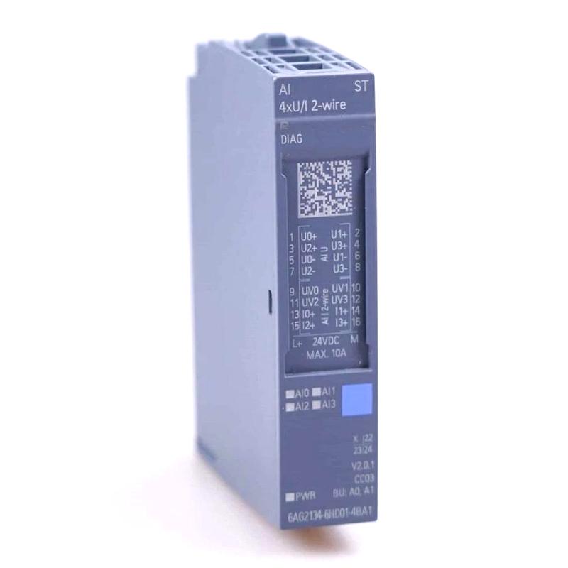
Siemens 6AG2134-6HD01-4BA1 Analog Input Module Troubleshooting Guide (Unstable Signal Fault Diagnosis)
Introduction
Unstable readings from a Siemens 6AG2134-6HD01-4BA1 Analog Input Module can affect process monitoring, alarm thresholds, and closed-loop control. When an analog value fluctuates unexpectedly, the cause may be an unstable field signal, electrical interference, a grounding problem, incorrect channel parameters, or a fault in the sensor circuit.
The most effective troubleshooting method is to compare the physical input signal with the value reported by the PLC. Confirm the exact module specifications and supported diagnostic functions before selecting electrical test methods or replacement hardware.
1. Determine Whether the Signal or PLC Value Is Unstable
Start by observing the affected channel during normal operation. Record the raw input value, the scaled engineering value, the associated alarm status, and the conditions under which the fluctuation occurs.
Determine whether the variation is present in the physical instrument signal or appears only after the value enters the PLC program.
If the physical signal fluctuates, investigate the transmitter, process conditions, power supply, and wiring.
If the physical signal is stable but the PLC value changes unexpectedly, examine the module configuration, channel assignment, scaling logic, and diagnostic information.
If several channels fluctuate simultaneously, investigate shared environmental or electrical causes.
If only one channel is affected, focus first on that instrument and its individual signal path.
This initial separation prevents unnecessary changes to the hardware configuration before the source of the fault is understood.
2. Inspect Analog Signal Wiring and Shielding
Analog signals can be sensitive to electrical interference, particularly in cabinets containing variable-frequency drives, switching power supplies, motors, and contactors.
With the relevant circuits safely isolated, inspect the affected signal cable and its terminations. Look for loose terminals, damaged insulation, poor connector contact, incorrect reference wiring, or an unsuitable cable route.
Check whether the cable is routed in accordance with the installation requirements for the actual signal type. Review the shielding and grounding arrangement against the approved electrical design rather than adding grounding connections arbitrarily.
If the fluctuation occurs when a nearby motor starts or a contactor switches, compare the timing of the disturbance with the equipment's operating sequence. This correlation can help identify an interference-related problem.
3. Verify the Transmitter and Input Signal
A fluctuating PLC measurement may originate in the field instrument rather than the input module.
Check the transmitter's local display, status indicators, and diagnostic records where available. Compare its reported value with the PLC reading and, when appropriate, measure the electrical signal using a suitable instrument and approved test procedure.
For a current-loop instrument, confirm that the loop supply remains within the transmitter's requirements under load. Inspect loop connections and verify that the instrument's output range matches the configured PLC input range.
If the transmitter output itself fluctuates, investigate the sensor, process conditions, instrument supply, and field wiring. Replacing the analog input module is unlikely to correct a signal that is already unstable before reaching the input terminals.
4. Review Channel Parameters and Signal Processing
If the physical signal appears stable, examine the engineering configuration and PLC program.
Verify the configured input type, measurement range, channel activation, and address assignment. Check whether the program uses the correct raw-value representation and whether the engineering-unit conversion matches the transmitter's range.
Also review the configured integration time or filtering options, where supported. Filtering can reduce short-term variations, but excessive filtering may delay the response to genuine process changes.
Do not use filtering as a substitute for correcting damaged wiring, an unstable transmitter, or an incorrectly configured channel. First establish that the physical signal is valid, then adjust supported processing parameters to meet the application's response requirements.
5. Field Case: Analog Reading Jumps When a Drive Changes Speed
A production line uses an analog transmitter to monitor a process variable. The PLC measurement is stable at low motor speeds but begins fluctuating whenever a nearby variable-frequency drive accelerates.
The maintenance engineer compares the PLC trend with the transmitter's local indication and checks the timing of the disturbances. The investigation then focuses on the signal cable route, shielding, grounding, and separation from drive-related power wiring.
An inspection reveals that part of the analog signal cable runs alongside a high-noise power cable. The installation is corrected according to the plant's electrical design and the requirements for the actual input interface. The engineer then repeats the speed-change sequence and compares the signal trend before and after the correction.
If the variation decreases significantly, the evidence supports an electromagnetic-interference-related cause. If the fault persists, the next checks should include transmitter supply stability, signal references, input parameters, and channel diagnostics.
6. Check for Ground Loops and Reference Potential Differences
Unexpected analog offsets or fluctuations can occur when connected equipment has different electrical reference potentials or when grounding arrangements do not follow the intended design.
Review the electrical drawings and determine how the transmitter, power supply, cable shield, and PLC input are referenced. Check for unintended connections introduced during maintenance or instrument replacement.
Do not disconnect protective earth conductors or arbitrarily change shield connections as a troubleshooting shortcut. Any grounding modification must comply with the equipment manufacturer's instructions and the site's electrical safety requirements.
If the installation uses an isolated signal interface or signal conditioner, verify that the device is compatible with the signal type and range and that its power and wiring arrangements are correct.
7. Use a Fault Pattern to Narrow the Cause
Symptom | Possible cause | Recommended check |
|---|---|---|
One channel fluctuates continuously | Sensor instability, poor connection, or channel issue | Compare transmitter output with the PLC value |
Several channels fluctuate together | Shared interference or supply disturbance | Check common supplies, cable routing, and grounding |
Reading changes during drive operation | Electromagnetic interference | Review shielding and cable separation |
Physical signal is stable but PLC value is wrong | Incorrect scaling or configuration | Verify channel settings and conversion logic |
Reading has a persistent offset | Signal reference, calibration, or scaling issue | Compare against a known reference |
Fluctuation appears after wiring maintenance | Incorrect terminal or shielding arrangement | Compare the installation with the approved drawing |
These patterns help prioritize tests but do not independently prove a hardware defect. Confirm the cause using measurements, configuration checks, and repeatable operating tests.
8. When to Replace the Analog Input Module
Consider replacing the Siemens 6AG2134-6HD01-4BA1 only after the sensor, field wiring, signal quality, input configuration, and available diagnostics have been investigated.
Before replacement, save the project configuration, diagnostic records, and relevant input trends. Verify that the replacement has the required hardware compatibility and follow the approved isolation procedure.
After installation, restore the documented channel parameters and repeat the test that previously produced the unstable reading. If the same fluctuation remains, continue investigating the external signal path and system environment.
A module replacement should be supported by diagnostic evidence rather than by an unstable PLC value alone.
9. Preventive Maintenance Recommendations
To reduce recurring analog input problems:
Inspect field wiring and terminals during scheduled maintenance.
Check signal cable routing near drives and switching equipment.
Verify transmitter power and output ranges.
Keep channel configuration and scaling records up to date.
Trend critical analog measurements to identify recurring disturbances.
Review grounding and shielding against the approved electrical design.
Record diagnostic messages and corrective actions for future comparison.
Reliable analog measurement depends on the entire signal chain, from the field instrument and wiring to the module configuration and PLC scaling. Troubleshooting each stage systematically helps identify the real cause, minimize unnecessary component replacement, and maintain stable process control.