Siemens 6SN1123-1AB00-0HA1 Power Module Installation Guide (Hardware Setup & Commissioning)
Introduction
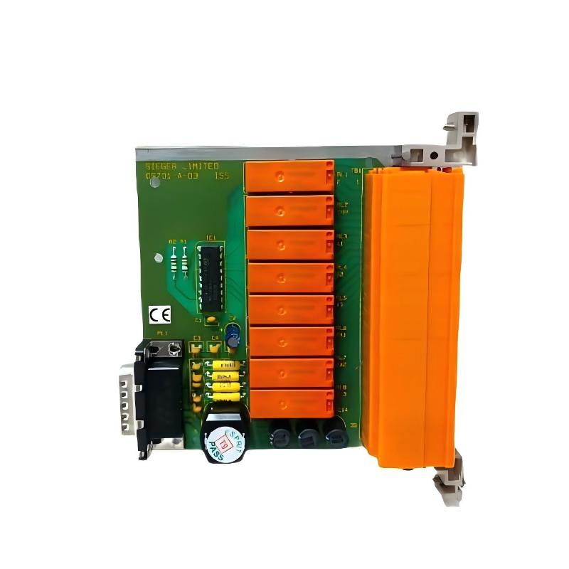
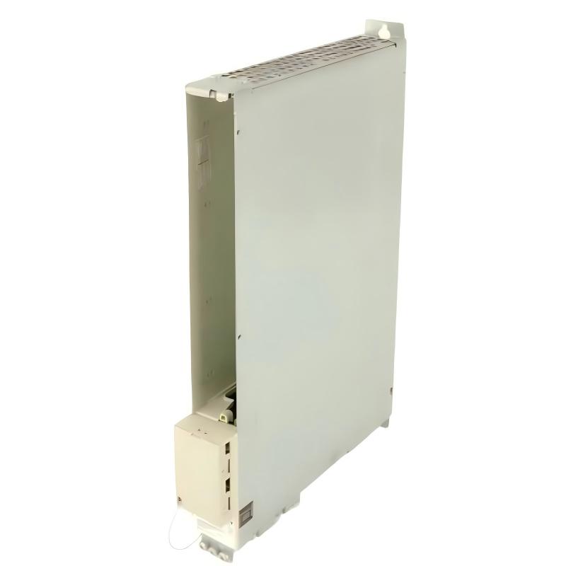
The Siemens 6SN1123-1AB00-0HA1 Power Module is associated with Siemens SIMODRIVE drive-system hardware used in industrial motion-control applications. Correct installation is essential for reliable drive operation, stable power delivery, and safe integration with the associated drive components. Before installation, confirm the exact module variant, supported drive configuration, electrical ratings, and compatibility requirements using the applicable Siemens documentation.
This guide covers installation preparation, hardware inspection, electrical connection checks, commissioning, and practical verification steps. Because power-module configurations can vary, do not assume that terminal assignments, supply requirements, or supported drive combinations are identical across different 6SN1123 variants.
1. Pre-Installation Checks for Siemens 6SN1123-1AB00-0HA1
Before installing the module, verify that it matches the approved machine design and the existing SIMODRIVE system configuration.
Check the following items:
Order number: Confirm that the module label matches 6SN1123-1AB00-0HA1.
Drive compatibility: Verify the supported drive arrangement and associated components.
Electrical ratings: Confirm the required supply, current ratings, and applicable protection requirements.
Physical condition: Inspect the enclosure, connectors, terminals, and mounting surfaces for shipping damage.
Cooling requirements: Check the specified ventilation, cabinet conditions, and clearance requirements.
System documentation: Review the electrical drawings, approved configuration, and relevant Siemens installation instructions.
If the module is replacing an existing unit, document the original connections and parameter settings before removing it. A replacement with a similar appearance may have different electrical or configuration requirements.
2. Safety and Hardware Installation
Power-drive equipment can retain hazardous voltage after the incoming supply has been disconnected. Before installation, isolate all relevant energy sources, follow the site's lockout/tagout procedures, and wait for the discharge period specified by Siemens. Verify the safe condition using the required measurement procedure.
Installation procedure
Confirm the designated mounting position and the module's compatibility with the installed drive system.
Inspect the mounting surfaces and electrical interfaces for contamination or damage.
Install the module using the prescribed mechanical arrangement.
Secure the module according to the applicable installation instructions.
Connect the required power and control interfaces using the verified wiring diagrams.
Check connector engagement, terminal identification, cable routing, and strain relief.
Verify protective grounding and any specified shielding arrangements.
Inspect the installation before restoring power.
Do not force connectors into place or modify wiring to accommodate an uncertain terminal assignment. If the module's exact connection details cannot be confirmed, resolve the documentation discrepancy before proceeding.
3. Electrical Connection and Cabinet Preparation
Reliable power-module operation depends on correct electrical integration and suitable cabinet conditions.
Before energizing the system, verify:
Incoming supply and protective-device arrangements.
Compatibility of connected drive components.
Correct power and control connections.
Protective-earth connections and bonding.
Cable routing and separation in accordance with the system design.
Cooling airflow and cabinet ventilation.
Tightness of accessible connections, following the prescribed torque specifications.
For a drive system that includes motors, feedback devices, or associated control electronics, check that the connected components match the approved configuration. Do not substitute components or change motor connections solely because their connectors appear compatible.
Also inspect the cabinet for dust accumulation, obstructed air passages, and evidence of overheating. Environmental problems can contribute to recurring drive faults even when the power module itself is functioning correctly.
4. Siemens 6SN1123-1AB00-0HA1 Configuration Checks
Before commissioning, confirm that the installed hardware matches the drive configuration documented for the machine.
Review the system's component arrangement, relevant drive parameters, and any documented configuration requirements. If the module is being replaced, compare the replacement configuration with the recorded baseline and identify any parameter differences that require approval.
The following checks are particularly important:
Correct identification of the installed module.
Compatibility with the associated SIMODRIVE components.
Consistency between the electrical drawings and actual connections.
Correct configuration of the relevant drive system.
Availability of required cooling and protective arrangements.
Absence of unresolved hardware or configuration discrepancies.
Avoid copying parameters from another drive or machine without confirming compatibility. Incorrect settings may prevent startup or affect motor behavior.
5. Commissioning and Functional Verification
Commissioning should proceed in stages, beginning with static checks and moving to controlled operation only after the installation has been verified.
Commissioning stage | Verification | Expected result |
|---|---|---|
Visual inspection | Check mounting, wiring, and connectors | No visible installation defects |
Grounding check | Verify protective-earth arrangements | Meets the approved electrical design |
Supply verification | Measure at designated test points | Within documented operating limits |
Initial power-up | Observe the system's documented status indications | No unexplained startup fault |
Drive diagnostics | Review the applicable diagnostic information | No unresolved installation-related alarm |
Controlled operation | Run an approved functional test | Drive responds as intended |
Stability test | Monitor operation under representative conditions | No recurring abnormal behavior |
All energized testing must follow the manufacturer's safety procedures. Measurements should be taken only at designated test points using suitable instruments and qualified personnel.
Do not run the motor or enable the drive until the mechanical system, motor connections, protective devices, and emergency-stop functions have been verified.
6. Field Case: Drive Fails to Start After Power-Module Replacement
A machine undergoing maintenance fails to start after its power module has been replaced. The maintenance team initially suspects a defective replacement unit.
The engineer first confirms the order number and checks the replacement against the approved drive configuration. The electrical connections and associated components are then compared with the original drawings. The diagnostic information indicates that the drive system has not reached its expected ready state.
Instead of repeatedly resetting the system, the team verifies the supply conditions, hardware compatibility, configuration records, and relevant drive interlocks. After the identified discrepancy is corrected, the drive is tested using the approved commissioning sequence.
This case highlights the importance of checking system integration and configuration before concluding that a newly installed power module is defective.
7. Installation Acceptance Checklist
Before returning the machine to service, confirm that:
The module identity and drive compatibility have been verified.
The mounting arrangement meets the installation requirements.
Power and control connections match the approved drawings.
Protective grounding and cable routing have been checked.
Cabinet cooling and environmental conditions are acceptable.
Relevant configuration settings have been verified.
Initial power-up and diagnostic checks have been completed.
Controlled functional testing has passed.
Installation changes and commissioning results have been recorded.
A documented installation baseline helps maintenance personnel identify future changes and reduces avoidable commissioning delays.