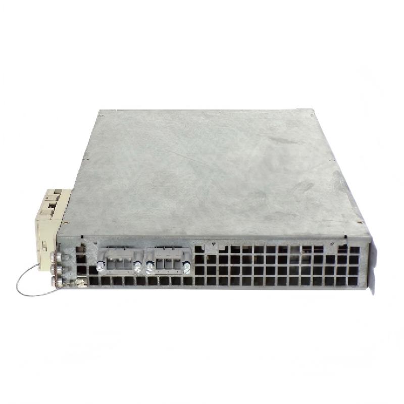
Siemens 6SN1123-1AB00-0HA0 Power Module Troubleshooting Guide (Drive Fault Diagnosis and Maintenance)
When a Siemens 6SN1123-1AB00-0HA0 Power Module is associated with repeated drive faults, unexpected shutdowns, or unstable machine operation, troubleshooting should begin with the system's diagnostic information rather than immediate component replacement. The objective is to determine whether the fault originates in the power supply, drive configuration, cooling system, motor circuit, or the module itself.
Because the precise fault indications depend on the complete drive configuration, engineers should use the applicable Siemens documentation to interpret alarms and establish the correct test points.
1. Start With Fault History and Operating Conditions
The circumstances surrounding a failure often provide the first useful diagnostic clue. Record the fault message, operating state, machine load, and events immediately preceding the shutdown.
Useful questions include:
Does the fault occur during initial startup or after the machine has been running?
Is it triggered by acceleration, deceleration, or a change in load?
Does the problem affect one drive axis or several?
Does the fault disappear after cooling, or does it remain after a restart?
Have there been recent changes to wiring, motors, mechanical loads, or drive parameters?
Avoid repeatedly resetting the system before recording the diagnostic information. Doing so may remove useful evidence or expose the equipment to further stress.
2. Troubleshooting Power Supply and Protective Circuit Problems
A drive fault associated with the power module may actually originate in the upstream electrical supply or a protective circuit.
Check the supply arrangement against the machine's wiring diagrams. Inspect the relevant fuses, circuit breakers, contactors, connectors, and accessible wiring for damage or signs of overheating.
Where electrical measurements are required, use the specified test points and instrument ratings. Compare the readings with the documented limits for the actual drive configuration rather than applying generic voltage thresholds.
Observed symptom | Possible cause | Recommended diagnostic action |
|---|---|---|
Drive does not start | Missing supply or unmet enable condition | Check supply status and the startup sequence |
Protective device trips | Electrical fault, overload, or incorrect protection arrangement | Isolate the equipment and investigate the protection circuit |
Fault appears during load changes | Supply disturbance or excessive load demand | Review diagnostic history and operating conditions |
Repeated faults after restart | Underlying electrical problem remains | Identify and correct the cause before resetting again |
If there is evidence of a short circuit, damaged insulation, or abnormal heating, keep the equipment isolated until the fault has been identified.
3. Diagnosing Intermittent Operation and Connection Problems
Intermittent drive faults can be difficult to reproduce because they may depend on vibration, temperature, or machine movement. Loose connections, damaged conductors, contaminated connectors, and poor cable routing should therefore be considered when the fault occurs irregularly.
With the system safely isolated:
Inspect accessible connectors for incomplete engagement or visible damage.
Examine cable insulation and strain-relief points.
Check for signs of discoloration, corrosion, or contamination.
Compare terminal and connector arrangements with the correct wiring documentation.
Verify that cable routing and shielding, where applicable, follow the machine's design.
Do not disconnect or reconnect drive components while energized unless the specific equipment documentation explicitly permits the operation. Never use improvised connector adjustments as a substitute for replacing damaged components.
4. Investigating Drive Faults During Acceleration or Deceleration
If the machine operates normally at a steady speed but faults during acceleration or deceleration, investigate the relationship between the fault and the mechanical operating cycle.
Potential causes include excessive load, a mechanical obstruction, incorrect motor-related configuration, unsuitable operating parameters, or a problem in the drive's power path.
A useful diagnostic sequence is:
Compare the fault timestamp with the machine's motion sequence.
Check whether the fault appears at a repeatable speed, load, or transition.
Review motor and drive configuration against approved commissioning records.
Inspect the driven mechanism for binding, excessive friction, or unexpected resistance.
Compare behavior with a known-good operating cycle, if the machine's safety procedures permit.
Do not increase current limits or alter protection settings simply to suppress a recurring fault. First establish whether the mechanical load, electrical system, and configuration are within their documented operating limits.
5. Distinguishing Module Faults From Motor-Side Problems
A drive fault does not prove that the Siemens 6SN1123-1AB00-0HA0 itself has failed. Motor cables, motor insulation, feedback-related components where applicable, and mechanical loads may produce symptoms that appear to originate in the power stage.
To narrow the diagnosis, compare the fault behavior with the available drive diagnostics and inspect the motor-side circuit under the appropriate isolation procedure.
Diagnostic observation | Area to investigate |
|---|---|
Fault occurs only on one axis | Axis-specific wiring, motor, configuration, or mechanical load |
Multiple drives fault together | Shared supply, common protection, or system-level conditions |
Fault appears at a repeatable motion transition | Load behavior, acceleration settings, and motor-side circuit |
Fault persists with the motor disconnected | Drive configuration and module-side diagnostics, subject to the manufacturer's test procedure |
Visible damage is present on the module | Stop testing and arrange qualified inspection or replacement assessment |
Disconnecting a motor or changing the circuit configuration should only be performed when permitted by the equipment documentation and the machine's safety procedure. Some tests require specific drive states or specialist equipment.
6. Field Case: Repeated Faults During Machine Acceleration
A production machine runs normally at low speed but trips when an axis accelerates to its normal operating rate. The maintenance team initially suspects the power module because the fault appears during a high-demand motion sequence.
The engineer reviews the fault history and discovers that the shutdown repeatedly occurs at the same stage of the machine cycle. After isolating the equipment, the team inspects the driven mechanism and checks the motor-side circuit against the approved documentation.
The investigation identifies abnormal mechanical resistance in the driven assembly. The resistance increases the demand on the drive during acceleration, triggering the system's protective response. After the mechanical problem is corrected, the team performs the required checks and repeats the controlled functional test.
The drive then completes the operating cycle without reproducing the original fault.
Diagnostic takeaway: A repeatable fault under acceleration may be caused by the mechanical load rather than a defective power module. Correlating diagnostic timestamps with the motion sequence can prevent unnecessary replacement costs.
7. When to Repair or Replace the Siemens 6SN1123-1AB00-0HA0
Replacement should be considered only after the supply, wiring, configuration, cooling, motor-side circuit, and relevant mechanical conditions have been evaluated.
Before installing another unit, confirm:
The replacement is an approved match for the installed drive configuration.
The original fault has been investigated and, where possible, its root cause corrected.
The relevant connectors and associated components have been inspected.
Any required parameter or configuration procedures are documented.
The post-replacement test plan follows the machine's safety requirements.
Power electronics should not be repaired by unqualified personnel. Internal components may retain hazardous energy, and improper repair can compromise electrical insulation, protective functions, and operational reliability.
8. Post-Troubleshooting Verification
After corrective action, verify that the original fault has been resolved and that the equipment operates correctly under representative conditions.
Test | Expected result |
|---|---|
Initial startup | Drive follows the documented startup sequence |
Diagnostic review | No unresolved faults associated with the original problem |
Controlled motion test | Axis responds as expected within approved limits |
Load transition test | Original fault does not recur under the tested conditions |
Thermal and visual inspection | No abnormal heating, odor, or visible damage |
Maintenance records | Root cause, corrective action, and test results are documented |
If the fault returns, compare the new diagnostic record with the original event. Differences in timing, load, or fault status may help isolate the remaining cause.
9. Preventive Maintenance for Siemens Drive Power Modules
Preventive maintenance should focus on identifying developing problems before they interrupt production.
Keep cabinet cooling passages and filters clean according to the maintenance schedule.
Monitor recurring drive alarms and investigate changes in fault frequency.
Inspect accessible wiring and connectors during scheduled, safely isolated maintenance.
Review the condition of upstream electrical protection and the cabinet environment.
Record operating conditions associated with intermittent or load-dependent faults.
Use approved spare parts and maintain accurate equipment configuration records.
A consistent troubleshooting process helps determine whether a fault is caused by the power module or by a related electrical, control, motor, or mechanical issue. This improves diagnostic accuracy, reduces unnecessary component replacement, and supports reliable operation of the wider Siemens drive system.