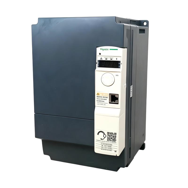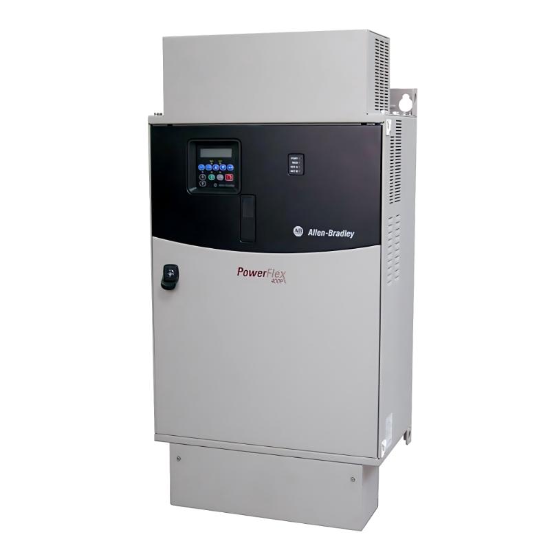
Allen Bradley 22C-D260A103 PowerFlex 400 AC Drive Installation Guide (Wiring, Setup & Commissioning)
The Allen Bradley 22C-D260A103 PowerFlex 400 AC Drive is a variable frequency drive designed for motor-speed control in fan, pump, and other industrial applications. Proper installation requires checking the drive's electrical ratings, motor compatibility, incoming power connections, grounding, and parameter settings before commissioning. Because this is a high-current drive, cabinet design, conductor sizing, overcurrent protection, and cooling arrangements are particularly important.
1. Allen Bradley 22C-D260A103 Technical Specifications
Parameter | Specification |
|---|---|
Product Family | PowerFlex 400 |
Model Number | 22C-D260A103 |
Drive Type | AC Variable Frequency Drive |
Application | Fan and Pump Control |
Input Voltage | 480V AC, 3-phase |
Input Voltage Range | 340–528V AC |
Rated Output Current | 260A |
Motor Power Rating | 132 kW / 200 HP |
Frame Size | G |
Enclosure Rating | IP30 / NEMA 1 |
Operator Interface | Fixed Keypad |
Communication | RS485 |
Brake IGBT | Not Included |
The 22C-D260A103 is a Frame G PowerFlex 400 drive. Frames G and H are designed for three-phase operation and should not be connected to a single-phase supply.
2. Preparing the PowerFlex 400 Drive for Installation
Before installing the 22C-D260A103, inspect the electrical cabinet, ventilation system, power distribution equipment, and cable routing.
The preparation process should include:
Confirming that the incoming supply matches the drive's voltage and phase requirements.
Checking the available short-circuit current and selecting suitable branch-circuit protection.
Verifying conductor sizes and terminal compatibility.
Preparing a reliable protective earth connection.
Separating motor power cables from low-voltage control and communication wiring.
Ensuring that the cabinet can dissipate the heat generated during continuous operation.
Do not select circuit breakers, fuses, or conductors based only on the drive's 260A output rating. Follow the manufacturer's installation requirements and applicable electrical regulations.
3. PowerFlex 400 Mechanical Installation and Wiring
Mechanical Mounting
The 22C-D260A103 should be installed securely in an approved electrical cabinet or suitable installation location. Maintain the manufacturer's specified ventilation clearances and ensure that cooling air can circulate freely.
Its IP30 / NEMA 1 enclosure rating does not make it suitable for direct exposure to rain, washdown water, or heavy dust. Additional environmental protection may be required depending on the installation location.
Incoming AC Power Connections
This model is designed for a 480V AC three-phase supply. Connect the incoming power conductors to the designated line terminals according to the wiring diagram.
Before energizing the drive:
Isolate and lock out the incoming power source.
Verify the supply voltage and phase arrangement.
Inspect all power terminals and conductors.
Tighten terminal connections to the specified torque.
Confirm protective earth continuity.
Remove loose wire strands, tools, and other foreign materials from the cabinet.
Never connect this Frame G drive to a single-phase power source.
Motor Output Connections
Connect the motor conductors to the designated drive output terminals. Before making the connection, check the motor nameplate for voltage, rated current, frequency, and winding configuration.
If the motor rotates in the wrong direction, isolate the equipment and correct the phase connections according to the manufacturer's procedure.
Do not install power-factor correction capacitors on the drive output. Any output contactors, reactors, or filters must be selected and installed according to the drive documentation.
4. PowerFlex 400 Control Wiring and RS485 Configuration
The PowerFlex 400 supports control arrangements suitable for fan and pump applications. Depending on the system design, the drive may receive commands from its keypad, external control terminals, or a supervisory controller.
Before connecting control wiring, determine the required operating method:
Local start and stop control.
External digital start/stop commands.
Analog speed reference.
Run and fault status signals.
RS485 communication with a PLC or building automation system.
Keep control cables away from high-current motor wiring. Apply suitable shielding and grounding practices where required.
For RS485 communication, configure the node address and communication parameters to match the connected controller. Check the network wiring and termination arrangement before commissioning.
5. Allen Bradley 22C-D260A103 Parameter Setup
Correct motor data is essential for stable drive operation. Enter the motor information according to its nameplate and the requirements of the application.
Configuration Item | Purpose |
|---|---|
Motor Rated Voltage | Matches the drive output to the motor |
Motor Rated Frequency | Establishes the motor's base frequency |
Motor Full-Load Current | Supports correct motor protection settings |
Motor Rated Speed | Helps establish the operating speed range |
Acceleration Time | Controls the motor startup ramp |
Deceleration Time | Controls the stopping ramp |
Minimum Frequency | Defines the lowest permitted operating speed |
Maximum Frequency | Defines the upper operating speed limit |
Start Command Source | Selects keypad, terminal, or communication control |
Speed Reference Source | Selects the required speed-command input |
Do not copy parameter values from another drive without confirming that the motor and application are equivalent.
Fan and Pump Application Settings
For centrifugal fans and pumps, motor load changes with operating speed. Appropriate acceleration settings can reduce mechanical stress and avoid unnecessary current peaks.
For pump applications, consider minimum speed, pressure requirements, flow limits, and the possibility of operating outside the pump's permitted range.
For fan applications, check minimum airflow requirements, ventilation interlocks, and damper operation.
6. Commissioning the PowerFlex 400 Drive
Before putting the drive into automatic operation, perform a controlled commissioning test.
Confirm that the motor is correctly connected.
Check that the driven equipment is mechanically ready.
Start with a conservative speed reference.
Verify motor rotation direction.
Monitor output current and motor operating conditions.
Increase the speed gradually.
Test normal stop commands and fault-response functions.
If the drive trips during the first run, record the fault code before resetting it. Repeated resets without identifying the cause can damage the drive or connected motor.
7. Common Installation Mistakes to Avoid
Several installation errors can cause unnecessary commissioning delays:
Incorrect supply configuration: The 22C-D260A103 requires a suitable three-phase supply.
Insufficient cabinet ventilation: Restricted airflow can cause excessive drive temperature.
Incorrect motor data: Incorrect voltage or current settings can affect motor operation.
Poor grounding: Improper grounding can create electrical interference and safety risks.
Incorrect cable routing: Motor cables installed alongside sensitive control wiring can introduce noise.
Unsuitable protection devices: Branch-circuit protection must follow the drive's technical requirements.
8. Installation and Commissioning FAQs
Q1: What type of applications is the 22C-D260A103 designed for?
It belongs to the PowerFlex 400 fan-and-pump drive family and is designed for variable-speed control in suitable industrial applications.
Q2: What is the rated power of the 22C-D260A103?
Its listed motor power rating is 132 kW, equivalent to 200 HP, with a rated output current of 260A.
Q3: Can the 22C-D260A103 operate from a single-phase supply?
No. This is a Frame G drive designed for three-phase operation.
Q4: What input voltage does this PowerFlex 400 model require?
It is a 480V AC three-phase model, with a published input voltage range of 340–528V AC.
Q5: Does the 22C-D260A103 have a built-in braking IGBT?
No. This catalog version is specified without a brake IGBT. Any braking requirements must be evaluated against the supported drive options.
Q6: What communication interface does the drive support?
The catalog configuration identifies RS485 communication. Confirm the required protocol and settings with the connected control system.
Q7: What should be checked before connecting the motor?
Verify motor voltage, full-load current, frequency, winding configuration, grounding, and compatibility with the drive's output rating.
Q8: Why is cabinet ventilation important?
The drive generates heat during operation. Insufficient cooling can lead to excessive internal temperature and protective trips.
Q9: Can motor parameters be copied from another PowerFlex 400?
Only when the motor specifications and application requirements are confirmed to be equivalent.
Q10: What information should be recorded during commissioning?
Record the drive model, motor nameplate data, parameter settings, supply voltage, operating current, communication settings, and any fault codes.