Allen Bradley 22B-D6P0H204 PowerFlex 40 AC Drive Installation Guide (Wiring, Setup & Commissioning)
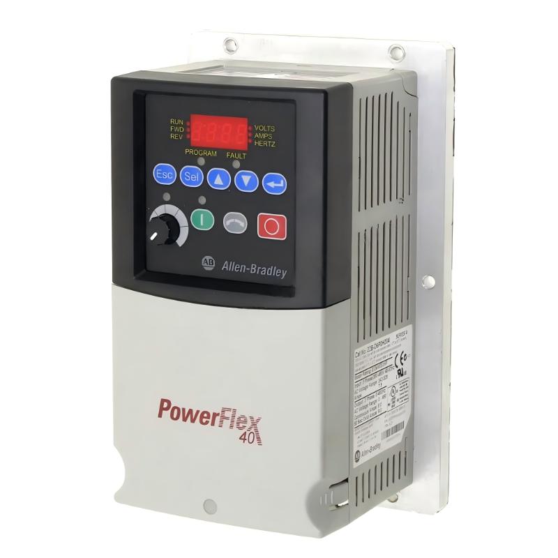
The Allen Bradley 22B-D6P0H204 PowerFlex 40 AC Drive is a compact variable frequency drive designed for industrial motor-speed control. It is commonly used in conveyors, pumps, fans, packaging machinery, and general-purpose automation equipment. Proper installation requires checking the incoming voltage, motor ratings, grounding, control wiring, and parameter configuration. Correct commissioning helps prevent nuisance trips, unstable motor operation, and premature equipment failure.
1. Allen Bradley 22B-D6P0H204 Technical Specifications
Parameter | Specification |
|---|---|
Manufacturer | Allen Bradley |
Product Family | PowerFlex 40 |
Model Number | 22B-D6P0H204 |
Drive Type | AC Variable Frequency Drive |
Input Voltage | 480V AC, 3-phase |
Rated Output Current | 6.0A |
Motor Power | 2.2 kW / 3 HP |
Frame Size | B |
Enclosure | IP20 / Open Type |
Control Method | Adjustable Frequency Control |
Communication | RS485 |
Application | Industrial Motor Speed Control |
The 22B-D6P0H204 belongs to the 480V-class PowerFlex 40 range. Before installation, verify the drive's complete catalog number and motor compatibility. Similar-looking PowerFlex 40 models may have different voltage classes and current ratings.
2. Preparing the PowerFlex 40 Drive for Installation
Before mounting the drive, inspect the electrical cabinet and confirm that the installation environment meets the drive's requirements.
Important preparation steps include:
Verify that the incoming power supply is compatible with the drive's rated voltage and phase.
Confirm that the motor's rated voltage and current are suitable for the drive.
Select appropriate branch-circuit protection according to the manufacturer's documentation.
Prepare correctly sized power and motor cables.
Provide a reliable protective earth connection.
Keep motor cables separate from sensitive control and communication wiring.
Ensure that sufficient ventilation space is available around the drive.
The 22B-D6P0H204 is an IP20 / open-type drive. It should be installed inside a suitable enclosure where it is protected from excessive dust, moisture, and accidental contact.
3. Mechanical Installation and Electrical Wiring
3.1 Mounting the Drive
The PowerFlex 40 can be mounted inside an electrical cabinet using the manufacturer's approved mounting arrangement.
Ensure that:
The mounting surface is stable and free from excessive vibration.
Cooling air can circulate around the drive.
The drive is not installed directly above equipment that generates excessive heat.
Power terminals remain accessible for inspection and maintenance.
The cabinet provides adequate space for cable bending and connection work.
Avoid installing the drive in an enclosed space without sufficient ventilation. Excessive operating temperature can reduce service life and cause protective trips.
3.2 Incoming Power Connections
The 22B-D6P0H204 is a 480V AC three-phase model. Connect the incoming supply to the designated line terminals according to the PowerFlex 40 wiring diagram.
Before energizing:
Isolate the incoming power supply.
Confirm the supply voltage and phase arrangement.
Inspect the power conductors for insulation damage.
Verify that the protective earth connection is secure.
Check terminal tightness according to the specified torque.
Remove loose wire strands and foreign objects from the cabinet.
Never connect incoming power to the motor output terminals.
3.3 Motor Output Wiring
Connect the motor to the designated U/T1, V/T2, and W/T3 output terminals.
Before connecting the motor, check its nameplate for:
Rated voltage.
Rated current.
Rated frequency.
Rated speed.
Winding connection.
The motor connection must match the drive output voltage and the motor manufacturer's instructions.
If the motor rotates in the wrong direction, isolate the power supply and follow the approved procedure for correcting the output phase connections.
4. Control Wiring and External Command Configuration
The PowerFlex 40 can operate through its built-in keypad or external control signals, depending on the application configuration.
Typical control arrangements include:
External start/stop switches.
Forward and reverse commands.
Analog speed references.
Digital preset-speed selection.
Relay status outputs.
RS485 communication with a PLC or supervisory controller.
Before connecting external signals, confirm the terminal functions and control-source parameters.
For analog speed control, check the signal type and reference range. For digital inputs, verify the assigned functions and electrical connections.
When RS485 communication is used, configure the drive address and communication parameters to match the connected controller. Keep communication wiring away from high-current motor conductors.
5. PowerFlex 40 Parameter Setup and Motor Configuration
Correct parameter configuration is essential for reliable motor operation.
The most important settings should be based on the motor nameplate and actual machine requirements.
Configuration Item | Purpose |
|---|---|
Motor Rated Voltage | Matches the drive output to the motor |
Motor Rated Current | Supports correct motor protection |
Motor Rated Frequency | Establishes the motor's base frequency |
Motor Rated Speed | Defines the motor's rated speed information |
Acceleration Time | Controls motor startup ramp |
Deceleration Time | Controls motor stopping ramp |
Minimum Frequency | Sets the lowest permitted operating frequency |
Maximum Frequency | Limits the upper operating frequency |
Start Source | Selects keypad or external command control |
Speed Reference | Selects keypad, analog input, or communication reference |
Do not use parameter values from another installation without confirming that the motor and application requirements are identical.
Application-Specific Configuration
For conveyor applications, acceleration and deceleration settings should account for belt inertia and material movement.
For pump applications, minimum and maximum speed limits should reflect the pump's operating range and process requirements.
For fan applications, verify minimum airflow requirements and any external ventilation interlocks.
6. Commissioning the Allen Bradley 22B-D6P0H204
A controlled commissioning process helps identify wiring and configuration problems before the machine enters production.
Recommended checks include:
Power-up inspection
Verify that the incoming voltage is correct and that no wiring or grounding abnormalities are present.
Motor data verification
Compare the configured motor voltage, current, and frequency with the motor nameplate.
Initial motor operation
Start the motor at a low speed reference and check its rotation direction.
Current monitoring
Observe motor current during acceleration and normal operation. Investigate abnormal current increases before continuing.
Control function testing
Test start, stop, speed adjustment, and any external interlocks.
Fault response
Verify that the drive responds correctly to stop commands and relevant fault conditions.
Record the final parameter settings and commissioning results for future maintenance.
7. Common Installation Problems to Avoid
Incorrect voltage selection: Connecting a 480V-class drive to an incompatible supply can damage the equipment.
Wrong motor parameters: Incorrect rated current or voltage can cause poor performance and protection problems.
Insufficient ventilation: High cabinet temperature may result in drive overheating.
Poor grounding: Improper grounding can introduce electrical interference and safety risks.
Incorrect control-source settings: The drive may ignore external start or speed commands if the command source is configured incorrectly.
Unsuitable acceleration settings: An excessively short ramp can cause high starting current or mechanical stress.
8. Installation and Commissioning FAQs
Q1: What type of drive is the Allen Bradley 22B-D6P0H204?
It is a PowerFlex 40 adjustable-frequency AC drive designed for variable-speed motor control.
Q2: What is the rated output current of the 22B-D6P0H204?
Its catalog rating is 6.0A.
Q3: What is the motor power rating of this model?
The listed motor power rating is 2.2 kW, equivalent to 3 HP.
Q4: What input voltage does the 22B-D6P0H204 require?
It is a 480V-class three-phase model. Confirm the permitted supply range on the product nameplate and technical documentation.
Q5: Can the PowerFlex 40 operate through external control terminals?
Yes. It supports external control arrangements, provided the relevant terminal functions and command-source parameters are configured correctly.
Q6: Can this drive communicate with a PLC?
Yes. Its RS485 communication interface can be used in compatible control-system configurations.
Q7: Why should motor nameplate data be entered before commissioning?
Correct motor data helps the drive operate within the motor's electrical ratings and supports appropriate protection settings.
Q8: What happens if the acceleration time is too short?
The drive may demand excessive current during startup or produce mechanical stress in the driven equipment.
Q9: Can the drive be installed without an electrical cabinet?
Its IP20 / open-type enclosure requires suitable environmental and contact protection. A suitable enclosure is normally necessary.
Q10: What should be checked if the motor does not start after installation?
Check the incoming supply, drive status, active fault codes, run-command source, terminal wiring, and motor connections.