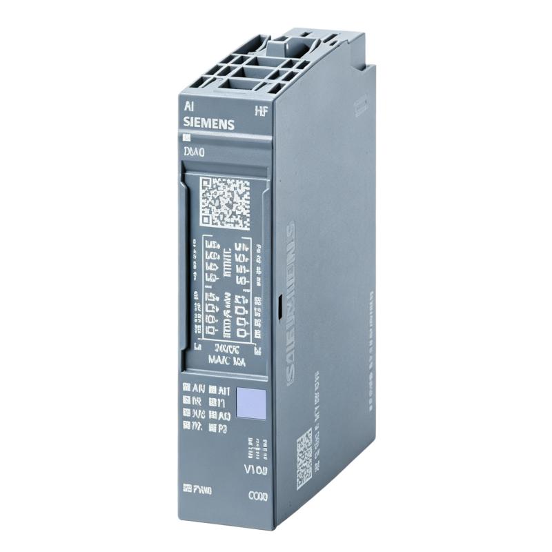
Siemens 6AG1134-6JD00-2CA1 Analog Input Module Installation Guide (Wiring & Commissioning)
Siemens 6AG1134-6JD00-2CA1 Analog Input Module installation problems are usually caused by incorrect sensor wiring, unsuitable signal configuration, grounding issues, or incorrect PLC parameter settings rather than module hardware damage. In industrial automation projects, analog input modules are responsible for converting real-world signals into PLC data, so installation accuracy directly affects process control reliability.
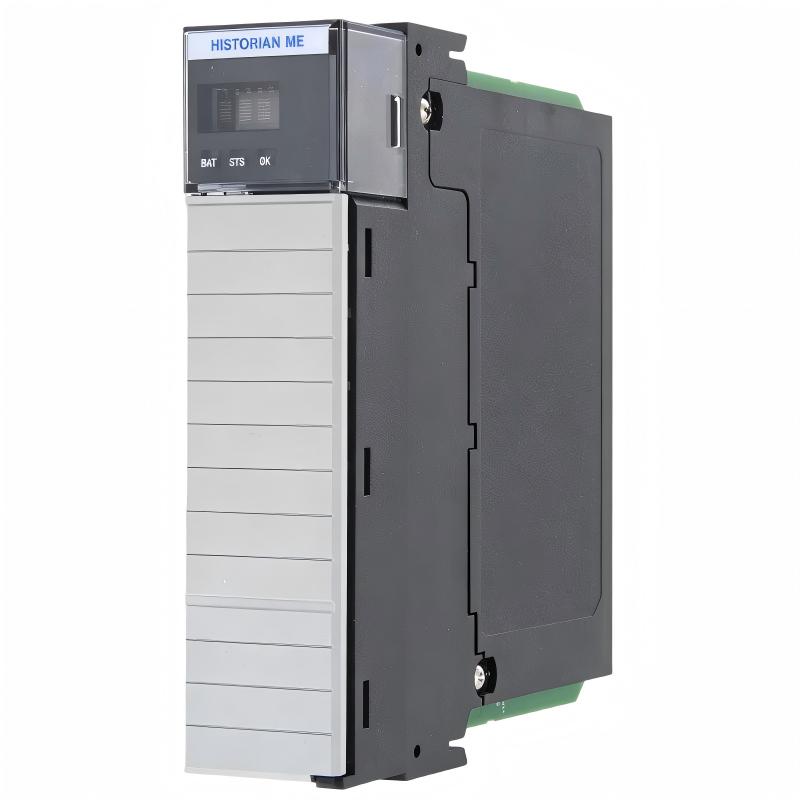
The Siemens 6AG1134-6JD00-2CA1 Analog Input Module is designed for SIMATIC automation systems requiring reliable acquisition of analog field signals. It is commonly used for collecting measurement data from industrial sensors such as temperature transmitters, pressure sensors, flow meters, and level monitoring devices.
Siemens 6AG1134-6JD00-2CA1 Analog Input Module Application and System Role
The analog input module creates the connection between field instruments and the PLC control system.
Typical signal path:
Industrial Sensor
       |
       |
Analog Signal (Current / Voltage)
       |
       |
Siemens 6AG1134-6JD00-2CA1 Analog Input Module
       |
       |
PLC Controller
       |
       |
HMI / SCADA / Process Control
The module is commonly applied in:
- Process automation equipment
- Manufacturing production lines
- Energy monitoring systems
- Machine condition monitoring
- Water treatment equipment
- Factory instrumentation systems
Typical connected devices include:
- 4–20 mA transmitters
- 0–10 V sensors
- Temperature measurement devices
- Pressure monitoring instruments
- Industrial flow sensors
In a real automation system, the accuracy of an analog measurement depends on the entire signal chain:
- Sensor output stability
- Cable quality
- Terminal connection
- Module configuration
- PLC scaling calculation
A problem in any part of this chain can appear as an analog input module fault.
Siemens 6AG1134-6JD00-2CA1 Installation Preparation Before Wiring
Before installing the module, engineers should confirm the complete measurement system.
Important preparation items:
- Verify sensor output type
- Confirm input channel configuration
- Check electrical specifications
- Review PLC hardware configuration
- Prepare shielded signal cables
Recommended inspection table:
| Inspection Item | Engineering Check |
|---|---|
| Sensor output | Confirm current or voltage type |
| Signal range | Match PLC configuration |
| Cable type | Use suitable instrumentation cable |
| Shielding | Confirm correct grounding method |
| Power supply | Verify stable control voltage |
A common field mistake is connecting a transmitter directly without checking the configured input range.
For example:
A sensor providing a 4–20 mA signal but configured as a voltage input may create:
- Incorrect process values
- Channel diagnostics
- Unstable control loops
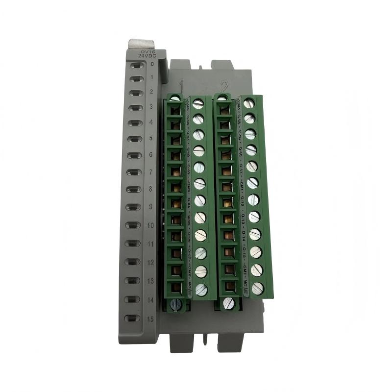
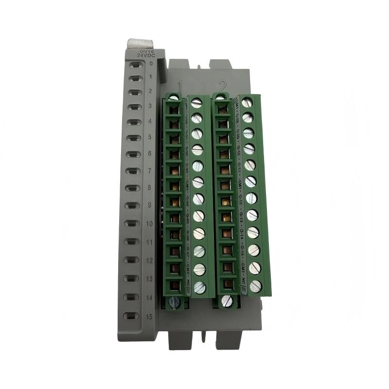
Siemens 6AG1134-6JD00-2CA1 Analog Input Module Wiring Installation
Correct wiring is critical for stable measurement.
Engineers should verify:
Sensor Signal Connection
Check:
- Signal positive terminal
- Signal negative terminal
- Sensor power supply
- Channel assignment
Incorrect wiring may cause:
- No measurement value
- Incorrect scaling
- Signal interruption
Siemens 6AG1134-6JD00-2CA1 Shielding and Grounding Setup
Analog signals are more sensitive to electrical interference than digital signals.
During installation, check:
- Cable separation from motor power lines
- Shield termination
- Cabinet grounding
- Cable routing
In one commissioning case, a Siemens 6AG1134-6JD00-2CA1 module was installed for monitoring hydraulic pressure.
Initial condition:
- PLC communication normal
- Module status normal
- Pressure value fluctuated between 4.8 bar and 6.5 bar
The field pressure gauge showed:
- Actual pressure: 5.2 bar
Engineers measured the transmitter output:
- Signal output: Stable 12.3 mA
Further inspection found:
- Analog cable installed beside a frequency converter output cable
- Shield connection was incomplete
After correcting cable routing and shielding:
- PLC pressure value stabilized at 5.2 bar
- False alarms disappeared
- Control operation returned to normal
The issue was caused by signal interference, not the Siemens analog input module.
Siemens 6AG1134-6JD00-2CA1 PLC Hardware Configuration and Parameter Setup
The hardware configuration must match the actual field device.
Important setup parameters:
- Input channel type
- Measuring range
- Diagnostic functions
- Signal filtering
- Address assignment
Engineering verification:
Sensor Specification
        ↓
Module Configuration
        ↓
PLC Raw Value
        ↓
Engineering Value
        ↓
Control Logic
If the raw value is correct but the engineering value is wrong, the problem is usually related to:
- Scaling parameters
- Conversion settings
- PLC program calculation
Siemens 6AG1134-6JD00-2CA1 Setup and Commissioning Procedure
Commissioning should verify the complete analog measurement path.
Recommended validation process:
Sensor Output Verification
Measure the actual field signal.
Example:
Pressure transmitter:
- Output: 4–20 mA
- Actual pressure: 8 bar
- Signal: 14.7 mA
PLC Input Verification
Check:
- Raw input value
- Engineering conversion
- Alarm limits
Control Response Testing
Verify:
- Process control reaction
- HMI display value
- Alarm operation
A successful commissioning result requires agreement between:
- Physical measurement
- PLC value
- Operator display
Siemens 6AG1134-6JD00-2CA1 Commissioning Validation and Performance Testing
Before releasing the system, engineers should complete:
- Channel-by-channel testing
- Sensor comparison
- Alarm verification
- Long-term signal observation
During a production test:
Before correction:
- Analog value drifted continuously
- Operators adjusted process settings manually
After correction:
- Signal remained stable
- Measurement matched field instruments
- Automatic control resumed
The Siemens 6AG1134-6JD00-2CA1 Analog Input Module installation process requires accurate wiring, correct configuration, and real field signal validation.