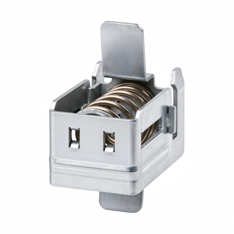
Siemens 6ES7590-5BA00-0AA0 Shielding Terminal Installation Guide (S7-1500 Wiring & Commissioning)
Siemens 6ES7590-5BA00-0AA0 Shielding Terminal Installation Guide for PLC System EMC Protection
Siemens 6ES7590-5BA00-0AA0 Shielding Terminal installation is mainly focused on correct cable shield bonding, EMC protection, and reliable signal grounding in S7-1500 PLC systems. In industrial environments, communication errors, unstable analog signals, and intermittent I/O faults are often caused by poor shielding practices rather than defective PLC modules.
The Siemens 6ES7590-5BA00-0AA0 Shielding Terminal is used as an accessory for S7-1500 installations to provide a defined connection point between cable shields and the system reference potential. Proper installation helps reduce electromagnetic interference (EMI) caused by motors, drives, contactors, and other industrial switching equipment.
A complete installation approach should consider:
Field Cable → Shield Connection → PLC Rack → System Ground → EMC Performance
This guide explains practical installation methods, wiring preparation, and commissioning checks for Siemens 6ES7590-5BA00-0AA0 in industrial automation cabinets.
Siemens 6ES7590-5BA00-0AA0 Shielding Terminal Installation Preparation
Before installing the Siemens 6ES7590-5BA00-0AA0, confirm the cabinet design, cable types, and grounding concept.
The preparation stage should verify:
- PLC rack installation position
- Available mounting space
- Shielded cable requirements
- Cable diameter compatibility
- Grounding arrangement
- Separation between power and signal cables
Typical applications include:
- Analog input/output wiring
- Communication cables
- Encoder connections
- Industrial sensor cables
- Distributed I/O connections
A shielding terminal should not be treated as a simple mechanical clamp. Its purpose is to provide a low-impedance path for interference currents.
During one S7-1500 cabinet commissioning project, several analog measurement channels showed unstable values despite correct module configuration. The first assumption was sensor failure. However, inspection showed that the cable shields were floating and not connected correctly at the PLC side. After installing the shielding arrangement correctly, the signal fluctuation was significantly reduced.
Siemens 6ES7590-5BA00-0AA0 Cabinet Mounting and Mechanical Setup
The physical installation location of the Siemens 6ES7590-5BA00-0AA0 Shielding Terminal affects EMC performance.
Before mounting, check:
- Correct position below the module area
- Secure mechanical attachment
- Proper contact with the mounting system
- Accessibility for maintenance
- Correct cable routing direction
The shielding terminal should be installed where the cable shields can reach it without excessive bending.
Avoid:
- Long unshielded cable sections near PLC modules
- Loose shield connections
- Mechanical stress on shield clamps
- Multiple uncontrolled grounding points
A practical cabinet arrangement is:
Signal Cable
     ↓
Cable Shield
     ↓
6ES7590-5BA00-0AA0 Shielding Terminal
     ↓
PLC System Ground
The shorter and cleaner the shield connection path, the better the high-frequency interference suppression performance.
Siemens 6ES7590-5BA00-0AA0 Shield Cable Connection Setup
Correct shield termination is the most important part of Siemens 6ES7590-5BA00-0AA0 Setup.
The technician should verify:
- Cable shield has sufficient exposed contact area
- Shield clamp contacts the conductive shield layer
- Connection is mechanically secure
- Shield is not connected through unnecessary long wires
For EMC applications, a large-area shield connection is generally preferred over a thin grounding wire.
A typical verification process:
Remove Cable Jacket
        ↓
Expose Shield Layer
        ↓
Position Shield Under Clamp
        ↓
Secure Mechanical Contact
        ↓
Check Continuity
        ↓
Document Connection
Do not remove more cable shielding than necessary. Excessive exposed conductor length can reduce EMC effectiveness.
Siemens 6ES7590-5BA00-0AA0 PLC System Configuration and EMC Considerations
Although the Siemens 6ES7590-5BA00-0AA0 is a passive accessory, its installation directly affects the overall PLC System Configuration.
Important system considerations include:
- PLC grounding concept
- Cabinet equipotential bonding
- Cable routing
- Drive installation
- Communication network design
A shielding terminal cannot compensate for poor cabinet design. For example, if signal cables run parallel with inverter output cables over long distances, interference may still occur even with correct shield termination.
A good engineering practice is to review:
Cable route → Shield connection → Grounding → Signal quality
rather than focusing on only one component.
Siemens 6ES7590-5BA00-0AA0 Commissioning Procedure and Validation
After installation, Siemens 6ES7590-5BA00-0AA0 Commissioning should include both mechanical inspection and signal verification.
Recommended checks:
Shield Connection Inspection
Confirm:
- Shield clamp is tight
- Cable shield has proper contact
- No loose wires exist
Electrical Verification
Check:
- Protective bonding continuity
- Correct grounding arrangement
- Absence of accidental short circuits
System Operation Test
Observe:
- Analog signal stability
- Communication reliability
- Diagnostic messages
- Noise-related faults
In one commissioning case, an engineer monitored an analog temperature signal before and after correcting shield installation.
Before correction:
- Signal fluctuation: approximately ±1.5°C
After correct shield bonding:
- Signal fluctuation reduced to approximately ±0.2°C
The PLC module was operating correctly; the issue was caused by EMC interference.
Siemens 6ES7590-5BA00-0AA0 Installation Case Study
A production machine using Siemens S7-1500 experienced occasional communication interruptions between control components.
Initial troubleshooting focused on:
- PLC CPU status
- Network configuration
- Communication parameters
All software diagnostics appeared normal.
Further investigation found that several communication cables had shields connected incorrectly and were not properly bonded through the shielding terminal.
The engineering team corrected:
- Shield contact position
- Cable routing
- Grounding connection
After correction:
- Communication interruptions disappeared
- Diagnostic alarms stopped
- System operation became stable
This case demonstrates that Siemens 6ES7590-5BA00-0AA0 installation quality can directly influence PLC system reliability.
Siemens 6ES7590-5BA00-0AA0 Shielding Terminal Maintenance Recommendations
For long-term operation, inspect:
- Shield clamp pressure
- Cable movement
- Corrosion
- Mechanical looseness
- Unauthorized wiring changes
During cabinet modifications, always update shield connection records. A new cable installation without proper shielding can introduce faults that are difficult to diagnose later.
The Siemens 6ES7590-5BA00-0AA0 Shielding Terminal should be installed as part of the complete EMC strategy of the S7-1500 PLC system. Correct mounting, shield bonding, and commissioning verification help maintain stable industrial automation performance.